This thread has been locked.

If you have a related question, please click the "Ask a related question" button in the top right corner. The newly created question will be automatically linked to this question.

DRV8305-Q1: DRV83055-Q1 operational temperature/ current amp

Part Number: DRV8305-Q1

Hi Sir,

My customer uses DRV83055-Q1 in water pump, two question need to be answered, thank you.

1. Operational temperature

In customer's board, the DRV83055-Q1 shows ~70 ℃ at the top surface in below condition, and it means the operational maximum ambient temperature is absolutely limited to ~80 ℃? Could you give me the maximum ambient temperature our EVM can work with? EVM's DRV8305N show ~60 ℃ in the same condition.

 Condition: 1) Room temp; 2) Connected to MOSFET, but without motor; 3)12V input; 4) LDO load ~7mA

2. Current sense amp

Could we use one of the current sense amplifier to sense the low side total current as below?
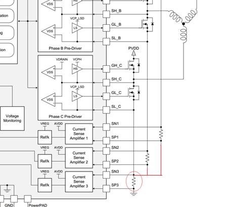
Best regards

  • Hi Jeremy,

    1.) Operational Temperature

    The recommended method for estimating the die junction temperature in our devices is:

    Tjunc = Tcase + (ψJT x Power)

    In this estimation, the ψJT value can be found in the DRV8305-Q1 datasheet and the Tcase measurement should be made by directly measuring the top of the case with an IR Camera or thermocouple.

    The estimated maximum ambient temperature would be approximately 80°C, however I would recommend making the measurement described above to determine the actual die temperature.

    Our EVM has not been tested extensively at high ambient temperatures so I unfortunately do not have a number to provide for this question.  Some important considerations for proper thermal dissipation are:

    • Thermal via stitching between top and bottom ground layers wherever possible
    • Continuous ground pours on top and bottom layers of PCB
    • Multiple thermal vias underneath power pad of DRV8305-Q1 tied to bottom layer ground plane

    2.)  Current Sense Amp

    Yes, you can use one current sense amplifier to sense total current.  The inputs of the two unused amplifiers (SNx and SPx) should be tied to ground and the two unused outputs (SOx) should be left floating.