This thread has been locked.

If you have a related question, please click the "Ask a related question" button in the top right corner. The newly created question will be automatically linked to this question.

DRV8711: Stepper Driver - Current Waveform Has Double Peaks

Part Number: DRV8711

Hey E2E,


I recently got a DRV8711 stepper driver board up and running.  Today I hooked the stepper motor up to a scope with a current probe, because I was noticing some bad vibration at pretty much all speeds and microstepping modes.


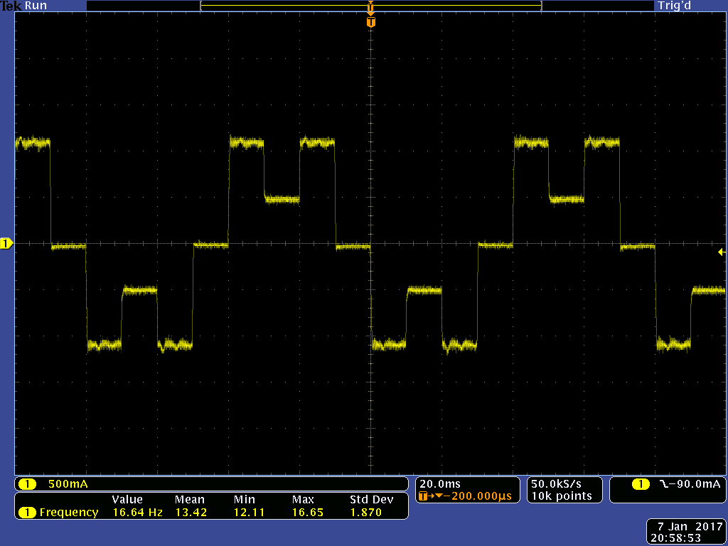
I found that the motor's current waveform has a strange double peak, kinda like the microstepping indexer gets reset to a previous value after topping the peak.  I'm sure that's not what's actually happening, but that's what it looks like.

This waveform was taken with 1/64th microstepping.  The double peaks are present all the way down to 1/2 microstepping, as shown in the next waveform.


With microstepping disabled, I get a good square wave, as expected.


During this testing, I was reading through the 'DRV8711 Decay Mode Setting Optimization' app note.  I was able to detune the driver to reproduce most of the issues listed, and then adjust it back to fix the issues, but through all this testing the only way I was able to get rid of the double peak was by bending the waveform so far out of shape that the motor squealed.


Has anybody experienced this before?

  • Hi Omacitin,

    Please examine the DIR pin and the nFAULT pin.

    The 1/2 step is strange because the current appears to be 0, 100% and 50%. The indexer is 0, 71% and 100%.

    What register settings are you using? What is the sense resistor value?
    Have you tried a second board?
  • Hi Rick,

    Thanks for getting back to me so quickly.

    I checked the DIR pin on the scope, and saw no significant noise.  It was switching only when the motor changed directions, as it should.

    The nFAULT pin was high.  The fault register showed only that a stall was detected, despite internal stall detection being disabled.  Resetting the register did not clear the stall flag.

    The sense resistors are 0.04 Ohm.  Those waveforms were taken with ISGAIN set to 40x and torque set to 255.

    From section 7.3.4 in the datasheet, I_FS = (2.75V * Torque) / (256 * ISGAIN * R_I_SNS).  So I_FS should be 1.71A.

    The current with no microstepping is 1.08A, which is close enough to the theoretical value of 1.71 * 71% = 1.21A.

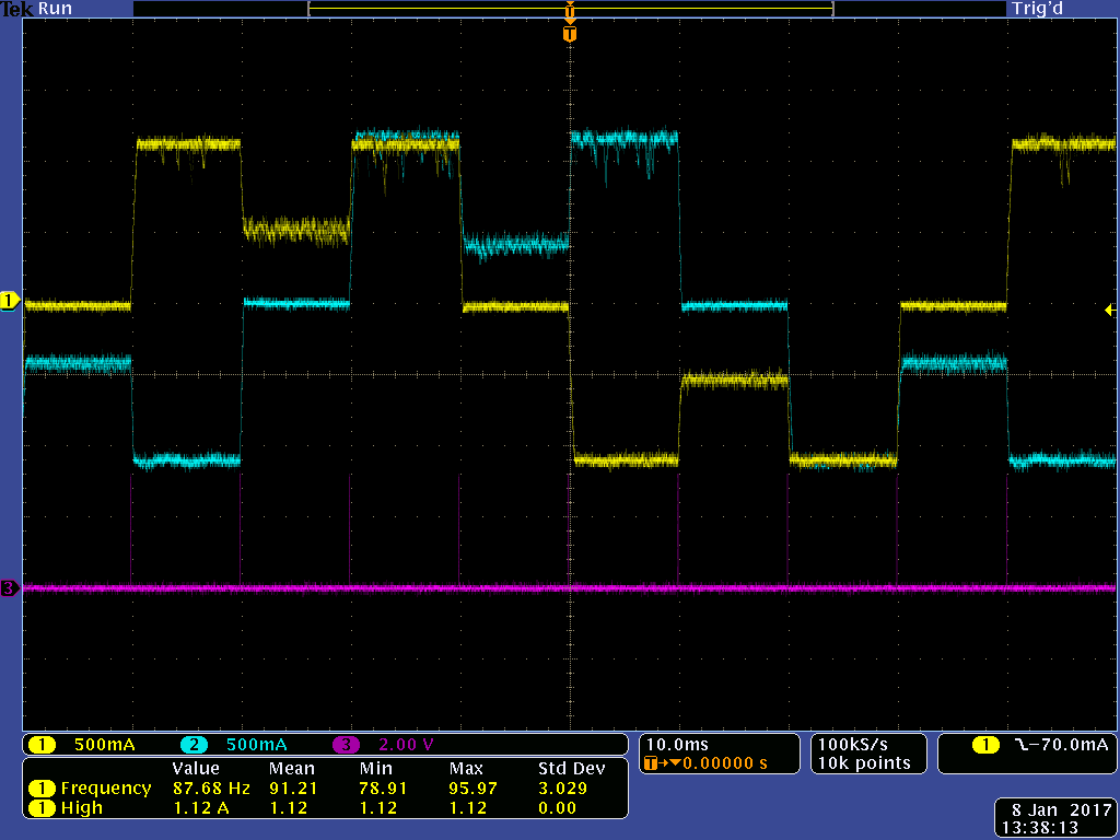
    Here's 1/2 microstepping with both phases and the STEP pin included:

    The current seems to be 0%, 71%, and 50%, like you said.


    Increased microstepping seems to follow the same pattern where it peaks at 71%, drops to 50%, then peaks at 71% again.


    Register settings for T_Blank, T_Off, T_Decay, and Decay Mode have varied all over the place during testing.  As long as the waveform is anywhere close to a sine, it has double peaks.  Adaptive blanking has no effect either.


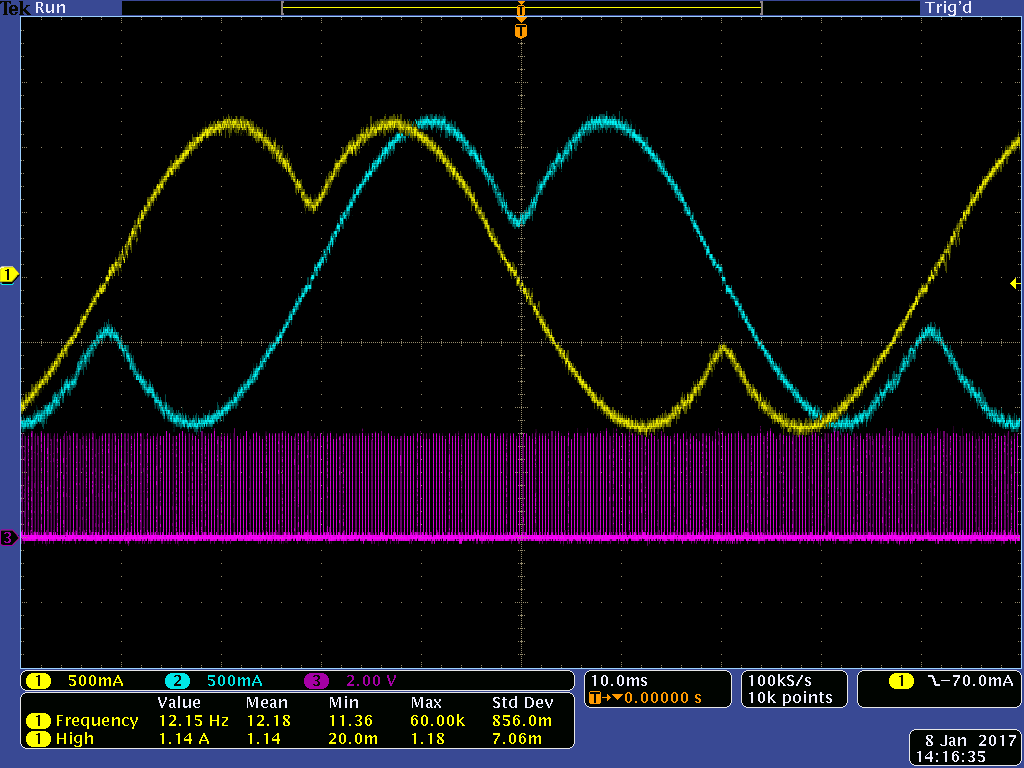
    This is 1/64th microstepping again:

    I haven't been able to test with another board.  This is the only one I have available at the moment.

  • Hi Omacitin,

    I have not seen current being regulated like this before.

    What is the VM voltage and current limit of the power supply?

    Can you provide the full step current scope captures?

    Please report the V5, VINT, and VCP voltages. Also please look at the RESET pin for noise.

    Using 1/2 step mode should not create the current waveforms captured. Assuming the voltage/motor resistance allows 1.7A current, the 1/2 step current waveforms should have match the currents listed in Table 4 of the datasheet. None of the current values shown match 1/2 step.

    Please let us know when you are able to test a second board.
  • Hi Rick,

    I think I found the problem while checking the pins you suggested.

    The VM and RESET pins were fine.


    The V5 pin was showing 4-6V high frequency noise.  I had left the cap off because the block diagram showed it as unconnected internally.  Silly.

    The VINT pin was showing a bit of that high frequency noise, probably because the two pins are right next to each other.


    I added the datasheet's 0.1uF cap to the V5 pin, which cleared up the noise on both pins and (mostly) the strange double peak waveform.

    The current waveform still has a very slight dip at the peak.  I'm going to guess that it's caused by either the abuse it's suffered or bad tuning.


    Thank you for the help, I really appreciate it.

  • Hi Omacitin,

    Glad to hear the problem has been solved.

    6V on the V5 output violates the absolute maximum voltage rating. The device may have been damaged.