This thread has been locked.

If you have a related question, please click the "Ask a related question" button in the top right corner. The newly created question will be automatically linked to this question.

DRV8833: Sleep pin question

Part Number: DRV8833
Other Parts Discussed in Thread: CC3200, , DRV8880

Hi, I'm about to use the DRV8833CPWPR.

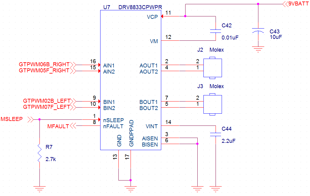
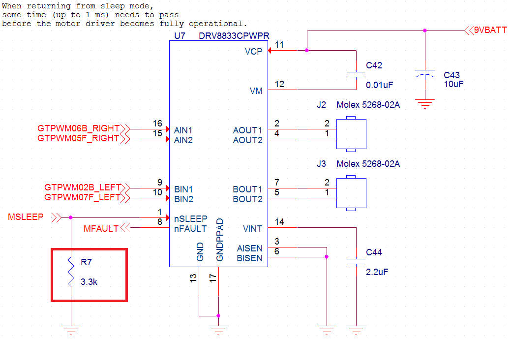
This is my current schematic. I use the 9V battery to power the motor driver.

I use CC3200 QFN MCU's PWM pins to control this.

My questions are,

0) The CC3200 operates with 3.3 volts. I've connected the nSLEEP pin to the CC3200's GPIO.

If I set the nSLEEP GPIO pin to high, which is 3.3V, does the motor driver runs (not sleeping)?

I can't find the threshold voltage value of nSLEEP pin to make the motor driver run.

1) Regardless of the value of AIN/BIN, is there no output when the nSLEEP pin is set to low?

The CC3200's GPIO pins start at HIGH after it is powered on. This causes the motor to run after the power is on.

So I hope to add a strong pull-down resistor (2.7k Ohm) at the sleep pin to use it as an "ENABLE" pin, instead of adding 4 pull-down resistors on each PWM pins.

If the nSLEEP pin is low, does the output of DRV8833 goes off?

2) Lastly, this motor driver causes heat. So I think this chip has to be apart from the CC3200 Wi-Fi MCU.

Is there a recommended "keep-out" distance when placing the DRV8833?

  • Hi David__ ,

    0) The CC3200 operates with 3.3 volts. I've connected the nSLEEP pin to the CC3200's GPIO.

    If I set the nSLEEP GPIO pin to high, which is 3.3V, does the motor driver runs (not sleeping)?

    -- When nSLEEP is set to high, the device is active. The outputs operate according to Table 1 of the datasheet.

    I can't find the threshold voltage value of nSLEEP pin to make the motor driver run.

    --- the nSLEEP pin threshold is listed in the datasheet (Vil < 0.5V and Vih >2.5V)

    1) Regardless of the value of AIN/BIN, is there no output when the nSLEEP pin is set to low?

    -- The outputs are disabled when nSLEEP is set to low. This is stated in section 7.3.4 of the datasheet.

    The CC3200's GPIO pins start at HIGH after it is powered on. This causes the motor to run after the power is on.

    So I hope to add a strong pull-down resistor (2.7k Ohm) at the sleep pin to use it as an "ENABLE" pin, instead of adding 4 pull-down resistors on each PWM pins.


    If the nSLEEP pin is low, does the output of DRV8833 goes off?


    -- Yes the outputs are off when nSLEEP is low


    2) Lastly, this motor driver causes heat. So I think this chip has to be apart from the CC3200 Wi-Fi MCU.

    Is there a recommended "keep-out" distance when placing the DRV8833?

    -- There is no recommended distance. The distance is dependent on the current through the DRV8833, the amount of copper to reduce the thermal, and the operational parameters of the surrounding devices.
  • Thanks for the detailed reply.

    I changed the pull-down resistor value.

    "Internally, the nSLEEP pin has a 500-kΩ resistor to GND"

    As stated above, I want to tie the sleep pin with a strong pull-down resistor so the motor doesn't start when powering up my CC3200.

    Does the strong pull-down resistor value can meet my desire?

    Since this product I'm designing is battery powered, the strong pull-down is a burden to me.

    So I wish to change the resistor value to save more battery.

  • Hi David,

    I am assuming you are concerned about the CC3200 Pad state after power up but prior to reset. Is that correct?

    I suggest you confirm the worst case pullup current with the CC3200 forum. This will allow you to properly size external pulldown resistor. You may find a 33k external pulldown will work.

    If it does, this will save a few mA when the device is active.
  • Hi, Rick.

    Rick Duncan said:
    I am assuming you are concerned about the Pad state after power up but prior to reset. Is that correct?

    Exactly! Thanks for your guidance.

    I'll replace my pull-down resister value, which was 3.3k, to 33k ohm.

    Deeply appreciative your help.

  • Hi,
    only because of interest - has anybody seen, that the VINT is connected to Ground. Is it possible? Or why should it be connected to VM?

    Best regards - Chris
  • Hi Chris,

    Are you referring to VCP?
  • Hello Chris,
    VINT pin should be connected to ground through a 2.2uF bypass capacitor. Thanks.
  • Hi Rick,

    yes you are right, it was my 'logical shortcut'.
    Nevertheless it is an interesting question for me: Why should I use a C from VCP to VM and NOT to Ground?

    Thank you

    Chris
  • Hi Chris,

    Connecting the C to VM instead of ground provides several benefits. Without going into all the details:

    There is less leakage in the capacitor when the charge pump is off. The voltage difference between VCP and VM is less.
    The voltage rating of the capacitor is lower. This is not noticeable in the DRV8833, but can be seen in the DRV8880. The capacitor rating is 16V instead of 63 to 100 when running at 45V.
  • Thank you Rick, this makes sense to me.
    And thank you for your rapid response.

    Best regards - Chris