This thread has been locked.

If you have a related question, please click the "Ask a related question" button in the top right corner. The newly created question will be automatically linked to this question.

DRV8838: DRV8838 Safe Operation Area

Part Number: DRV8838

Hello Motor driver team,

My customer is asking about safe operation condition not to damage FETs in H-bridge output of DRV8838.

Some condition of Vin or load impedance makes undesired overshoot and undershoot on output waveform during H-bridge switching.

My customer wants to know how much overshoot or undershoot DRV8838 output FET can withstand without damage risk.

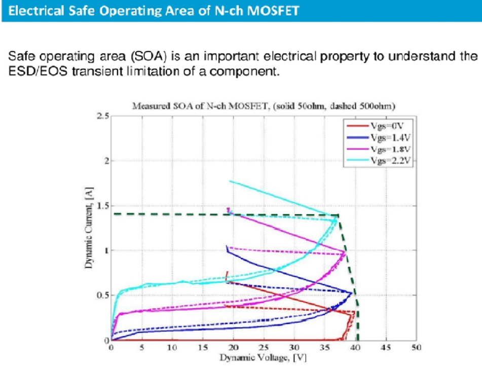
What is the maximum overshoot/undershoot voltage? My customer is asking about SOA(safety operation area) of FETs in H bridge. An  example is attached.

Here's their test data with 6V input and various PH pin signal(frequency and duty) in customer application. Is it safe operation for DRV8838?

11.5 ohm

6V

30khz

70khz

100khz

duty

10%

50%

90%

10%

50%

90%

10%

50%

90%

Overshoot

Max

7.16

7.08

7.16

8.04

7.16

7.24

8.6

8.76

7.08

Undershoot

Min

-0.6

-0.84

-0.92

-0.6

-0.84

-0.44

-0.52

-0.84

-0.84

Thank you.


  • Hi Kenneth,

    We do not provide a SOA curve because the Vgs is controlled internally by the DRV8838. Also there is protection against over temperature and over current.

    Typically the overshoot can exceed Vcc by 0.7V and the undershoot can be -0.7V below GND. The overshoot is less than the recommended maximum and the undershoot is in the expected range.
  • Hello Rick,

    Thank you for your answer.

    The overshoot/undershoot test result in table is measured with Vcc=Vm=6V.

    If overshoot should be less than Vcc+0.7V and undershoot should be higher than -0.7V, the data show already DRV8838 works in danger(8.76V and -0.92V).

    Did you mean the Vcc is in absolute maximum value in the datasheet? 12V in Vm? or 7V in Vcc?

    Please advise. Thank you.

  • Hi Kenneth,

    It is important to measure the overshoot/undershoot with respect to the proper pin and at the proper locations. Ideally a differential probe should measure the output with respect to pin 1 and pin 8 for overshoot, and the output with respect to pin 4 for undershoot. If this is not available, the math function within the scope can also work if the probe grounds are connected at the same location.

    I suspect VCC/VM are both rising during the overshoot time. If VCC rises above 7V, this should be addressed.

    Please ask for scope captures showing the overshoot and undershoot.