


Hello,
I'm trying to test the maximum phase current the DRV8332 can drive in our design, and I'm experiencing a behaviour that I don't understand. When going to large currents, the device is actively chopping the current whenever it surpasses a certain threshold. This threshold appears to be greater with a bigger heatsink attached, so I assume is not a OC protection limitation, but a over-temperature protection. This chopping is occurring at an audible frequency, so I need to get rid of it. The following capture can be explanatory:
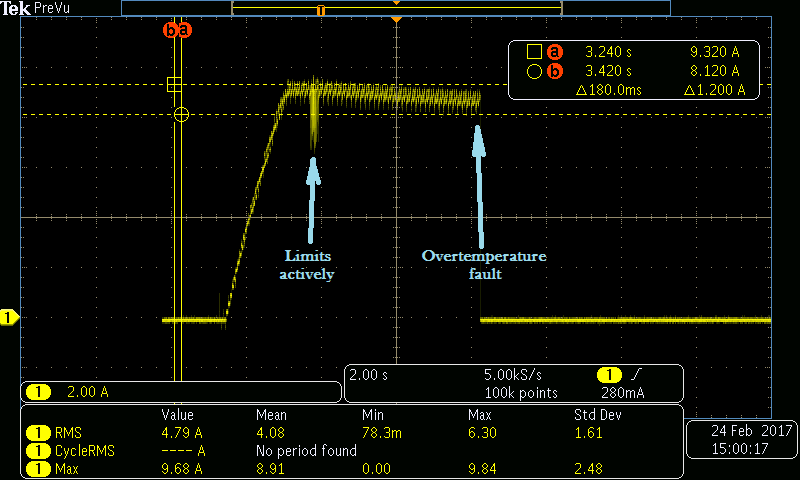
This was captured while driving a DC motor, after applying a ramp ending in a fixed dutty. The current goes to a maximum at the end of the ramp, and then decreases due to the increase of the Rds-on because of an increasing temperature. An OC even would have happened here, I think. But it happens a second after, which I can only associate with a thermal issue. It chops actively for a wile and, as thermal dissipation is not sufficient, OTE finally happens in about 5 seconds.
The OC is configured CBC limit not latching, so this was my first suspect, but the OC_ADJ is connected to a 19.6 kΩ resistor, and this is limiting way under 13 A.
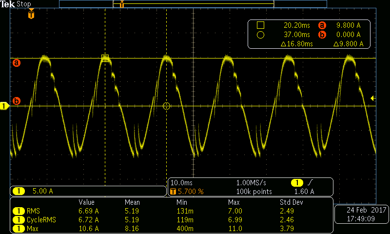
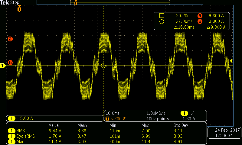
This other capture was taken while controlling a BLAC motor. When the peak (crest) value of the sinus is 8.6 A, the signal is clean and beautiful (good job inside there ;). But when it increases over this threshold (9.8 A in the image), it starts chopping continuously. This can last for a lot of minutes, and no OC or OTE event gets to happen. If the current demand increases a lot more, this chopping gets massive, as shown in the following image, and the sound is very annoying. The RMS value of the current is kinda kept constant, as the sinus changes its shape:
It is generating a 60 Hz sinus by a PWM of 20 kHz. I am using a big 1.2 ºC/W heatsink here, but also tested 5 ºC/W and 7.5 ºC heatsinks and for each one the phenomenon started at lower current, which re-enforces my theory that this is a thermal phenomenon.
Could you explain this behaviour? Is there any way I can avoid it?
Thanks a lot in advance!
