This thread has been locked.

If you have a related question, please click the "Ask a related question" button in the top right corner. The newly created question will be automatically linked to this question.

DRV8825: motor driver not work after 2nd time power up...

Part Number: DRV8825

Dear Sirs,

My customer use DRV8825 for their motor driver.

As customer feedback, while the first time power up, the driver and motor work fine.

However, they must delay next power up from first time, otherwise, the driver will no output then the motor cannot work.

The delay time needs around 10~20sec.

Once power up from long time power off, the first time must work without issue.

Please help to give me some advice for troubleshooting.

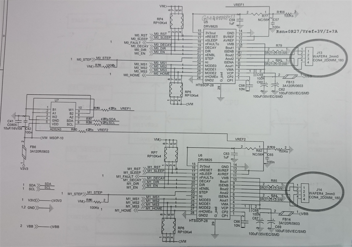
The customer schematics as attached file.

Thanks.


  • Hi Peter,

    Did the nFAULT assert during the second power up?

    Why is the device being powered down?

    Did the motor stop? Did the nFAULT assert? If the device is being powered down to recover from a fault, the voltage may not have been low enough.

    Please examine VM as the during power down, and report the voltage at different times during power down. A scope capture of the power down would also help.

  • Hi Sir,

    Thanks for reply!
    After checked with customer, if they used adaptor input(12V/3A), the driver did not have output and motor cannot work even first time power on. While using power supply input, the first time will OK.
    Is there any modification for schematics?
    Thanks.
  • Hi Peter,

    What is the VREF voltage?

    What is the DECAY setting?

    Is the fault pin asserting when attempting to run? If so, please see section 8.3.7 for possible causes.

    What are the motor specifications (model, R/ L / I/ V ratings)?

    Can you provide scope captures of the current when running the motor?

    The schematic looks ok.

  • Dear Sir,

    The result as below.

    The customer product is camera with up-down, and left-right motor control!

    Since the camera is not for security but for consumer, that is why they need to turn on/off the system. 

    =========================== 

    What is the VREF voltage?

    [Peter] 3.3V

    What is the DECAY setting?

    [Peter] 3.3V

    Is the fault pin asserting when attempting to run? If so, please see section 8.3.7 for possible causes.

    [Peter] according to customer design, the nfault pin was connected with MCU and always keep "low" ,even in good system. 

    What are the motor specifications (model, R/ L / I/ V ratings)?

    [Peter] The motor spec. as attach file.

    Can you provide scope captures of the current when running the motor?

    [Peter] while testing in customer side, there is no waveform output and motor cannot turn on.

    Since customer cannot lend motor to me except PCB, I just test PCB without motor attached in my side!

    In such situation, I can see the waveform from the output channel, but the power supply(12V or 15V input for VM) only output very small current.

    If I want to use E-load to simulate motor loading, which mode should I use?

    Thanks.

  • Hi Peter,

    Please ask the customer to:

    1) Change VREF to .8V -- This will reduce the current through the recommended 0.6A

    2) Add a pullup resistor to the nFAULT pin -- this will allow observation of device faults. The nFAULT pin is an open drain output and requires a pullup to see a logic high.

    3) Confirm the VM voltage of the pullup resistors is less than 7V -- ideally the voltage should be equal to or less than the mcu voltage