This thread has been locked.

If you have a related question, please click the "Ask a related question" button in the top right corner. The newly created question will be automatically linked to this question.

BOOSTXL-DRV8301: How to boot from flash -- read almost everything but can't get it to work

Part Number: BOOSTXL-DRV8301
Other Parts Discussed in Thread: LAUNCHXL-F28027, MOTORWARE

Hi,

I've been up and down the information highway including this forum all day but still can't boot from Flash.

This must be something very simple and I'm sure I will feel like a complete idiot when the penny finally drops but here goes...

I'm working with:

BOOSTXL-DRV8301 + LAUNCHXL-F28027 and

CCS 5 + motorware-foc

Specifically:

C:\ti\motorware\motorware_1_01_00_12\sw\solutions\instaspin_foc\boards\boostxldrv8301_revB\f28x\f2802xF\projects\ccs5\proj_lab05b

I've modified the project so I can read two GPIO inputs (16&17) and one ADC channel (B6) and use them to control 

  gMotorVars.Flag_enableSys 

  gMotorVars.Flag_Run_Identify 

  gMotorVars.SpeedRef_krpm  

so that I do not need the debugger to be able to start the motor and control the speed.

Works like charm when launched from with CCS debugger.

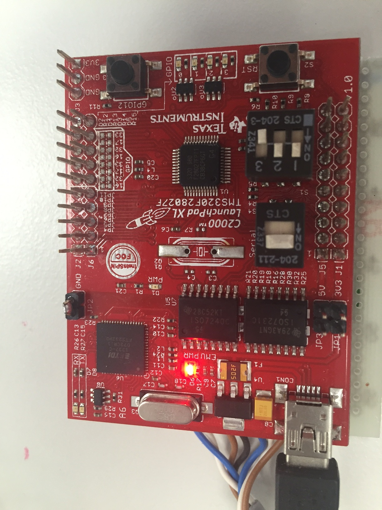
If I set the boot mode switches as in attached picture (1=ON/UP, 2=ON/UP, 3=OFF/DOWN)

remove USB cable and power cycle the system the software does not start.

But as soon as I connect the USB cable the software starts (no need to start the debugger,

in fact, if I connect the USB cable to my Mac that is enough enough to induce the Launchpad

to boot from the Flash).

So I think I've got the program happily in the Flash and it can be run from there and it does

not need any interaction with/via the debugger but something

is wrong with my boot switches or some settings in the project, though from what I've read

I think the lab05b project should 'just work' with the correct boot switch settings.

I've read just about everything in this forum and TI documentation that I can find related to

this issue but have not been able to solve this.

I found an almost identical post in the forum about this issue but no cure.

All tips highly appreciated.

I can include the project files if that helps and if someone can tell me what files to include and where to find them ...

me and the way TI organises the stuff on the disk don't get along ;)

cheers Kusti


  • Hi Kustaa,

    Our experts have been notified and should reply soon.
  • Alright Kusti,

    Let's begin with the reference I have utilized to assist you:

    1. Table 8: Stand-Alone boot Modes with (TRST = 0) on Page 22 / 52 of the  TMS320x2802x Piccolo Boot ROM Reference Guide

    http://www.ti.com/lit/ug/sprufn6a/sprufn6a.pdf

    Reference 1 shows the correct setup in hardware/software to boot in Stand-Alone Mode with our MCU. Stand-Alone means no external emulation controller is connected.

    We need GPIO37 and GPIO34 both High and TRST' low, which you have set up. This allows us to enter GetMode Mode. The default boot behavior is to flash unless the OTP is reprogrammed.

    Table 8 shows that:

    0x0D00 and 0x0D01 are don't cares

    0x3D7BFE does NOT equal 0x55AA

    0x3D7BFF is a don't care

    With these values, Boot Up should start in Flash Mode. Can you verify the values of these memory addresses are correct upon boot up?

  • Hi,

    thanks for getting back to me.

    I will check the memory values when I'm back at the office tomorrow, it is past 10 PM here in Finland so I'm home atm.

    I can probably figure it out how to verify those memory addresses when back at the office but just in case and because of time difference I could do with some hand holding so can you outline how do I verify those values and at which point?

    wbr Kusti
  • Alright Kusti,

    While running Code Composer Studio, set a breakpoint before the execution of any instructions stemming from your own main source code.

    Once the breakpoint is reached, go to View -> Memory Browser.

    From there, look for the memory addresses mentioned.

    I will try to replicate this suggestion on my end.
  • Great, thanks, looks straightforward, will get back to this in the morning. Goodnight!
  • Quick follow up: is it possible for you to save your project outside of your CCS workspace, uninstall Motorware v1.01.00.12 and install version v1.01.00.17? Not only does Motorware have this version update, but lab05b is now on Rev. D instead of Rev. B.

    I have access to the latest version.
  • Hi,

    as far as I understand, the memory setup looks good, see attached screen shots.

    As to updating to a newer motorware, unless there is a compelling reason/promise of

    solving this issue, I'm not too keen on that. In my experience that easily lends to 

    hours of works and I'm so close to get to what I'm doing atm with the current setup

    that I would rather just get my code to run standalone and proceed with the evaluation

    of the motor in the actual mechanics. Once we we start real coding, then sure.

    I just realised that I probably should do a hello world LED test so I can

    be sure that it is not something else than boot issue. I mean atm I know

    the motor does not respond to my ADC input or switches when I try to

    run standalone but of course could be something that works in debug mode

    and not as standalone.

    I've used the only usable LED output on Launchpad for input, I guess I need

    remove that to do a quick test.

    wbr Kusti

  • Alright Kusti,

    The reason why an upgrade to the latest Motorware can be essential is expanded program memory for the ramfuncs section in the F28027F.cmd file

    See image below:

    Now, I found an e2e post that gets this MCU running from flash. His struggle was getting the code to fit into the available memory and had to modify the .cmd file to get it to work.

    https://e2e.ti.com/support/microcontrollers/c2000/f/171/t/247599#pi316717=1

    In that e2e post Michael details the changes he made to the .cmd file in case we require such changes.

    Best suggestion right now is to create the hello world LED program and run the device in stand alone.

    I am trying to fit some time to actually run code from flash over here.

    After flash works, we can verify the ADC input issue you mentioned.

  • Solved. 

    Upgraded the motorware ... no help but mercifully simple.

    Then the penny dropped.

    I used the 'debug' button as a short cut to connect to the target and flash the code because it is just one click instead of launching a configuration, connecting target, loading flash.

    Unfortunately I did not appreciate that after clicking the cute bug icon the CCS place a break point in the code that does not get removed unless I disconnect the target. Or something like that ...

    now when I click 'debug' and then disconnect target the flash gets programmed and the code runs standalone if the dip switch is set as in my first picture.

    How embarrassing --- but thought I owed it to everyone to share this conclusion.

    Thanks!

  • Hey Kusti,

    There you go. These events happen to everyone!

    Please let us know if there are any issues with the ADC inputs.