


I am using the DRV8825 driver to microstep a stepper motor in a circuit with the following parameters:
- Motor coil resistance: 2.5 Ohms
- Motor coil inductance: 2.5 mH
- Motor supply voltage: 28 V
- ISENA/ISENB resistance: 0.220 Ohms
- Current setting: 1 A
- Decay mode: fast
The motors successfully rotate given step commands. I do not have a current probe for my scope, so to verify microstepping operation, I attempted to make a measurement across each coil's current sense resistor. When the H-bridge applies power across the coil, the voltage on the sense resistor is proportional to the winding current, since it is in series with the motor. Since we are using fast decay mode, this is also true during decay, however, the polarity through the coil swaps, so I need to be aware that the voltage at the sense resistor will invert. Taking that into account, I expected to see a waveform similar those in the DRV8825 manual for the front half of each PWM cycle, with more severe fall rates due to the fast decay vs. slow and mixed shown in the datasheet.
However, I'm seeing the following voltage trace at ISENA with the motor holding:
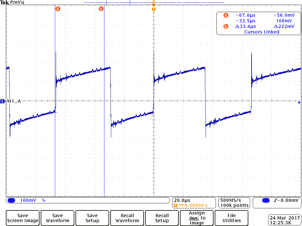
The most confusing thing is that there are segments exceeding the 33.3 us that the 30 kHz PWM would chop at. Is it not possible to analyze the current draw behavior using the sense resistor voltages? Am I misinterpreting the meaning of this trace?
