This thread has been locked.

If you have a related question, please click the "Ask a related question" button in the top right corner. The newly created question will be automatically linked to this question.

DRV8701: DRV8701: use in 1/2 bridge mode for 2 motors?

Part Number: DRV8701

Hi TI team!!!

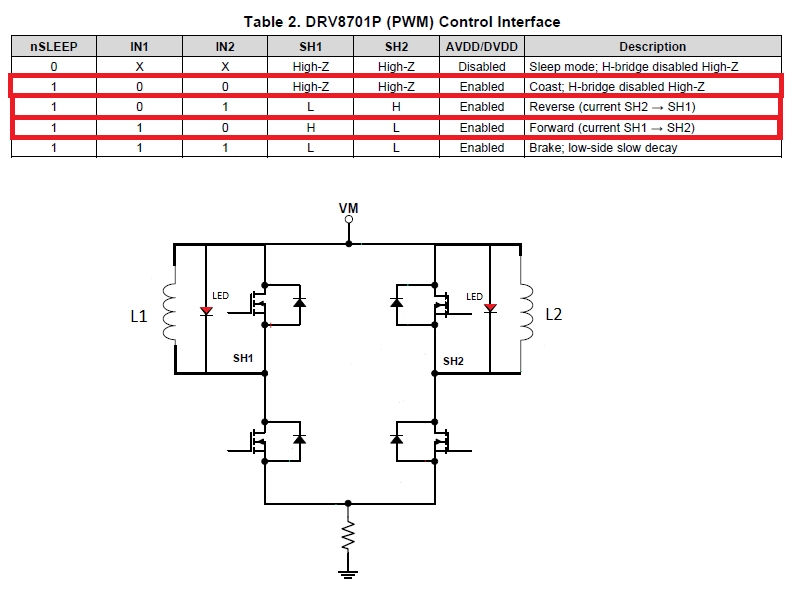
     I saw this question in the support forum before but the main difference is that I don't want to use both motors at the same time.   I'm using DRV8701P motor driver.   Since I want to keep OC detection (through the shunt resistor tied to SP and SN pins), both motors were connected to VM: one from SH1 pin to VM and the second from SH2 pin to VM.   As I said before, only one will work at the time.   I saw control interface table (truth table) and it is possible to do it (in theory), but for some reason, when the input pins (IN1, IN2) go low (High-Z impedance at the output) an indicator leds in parallel with the motors turn on.   It is strange to me since it is supposed to have high impedance to VM or floated, and no current must flow (not the enough current to turn on the led).  Am I using the IC correctly?  Is it possible to use this IC in this way?   Unfortunately I can't change this component.

     Thanks in advance for your help.

  • Hi Felipe,

    We will investigate and reply. This may take a few days.
  • Hi Felipe,

    Can you clarify a few items?

    1) Since I want to keep OC detection (through the shunt resistor tied to SP and SN pins) -- Do you mean OC using the VDS monitor defined in section 7.3.13.3 or current regulation defined in section 7.3.3? OC detection can be set for either the high side or low side FETs. Current regulation may create problems because slow decay is entered. This keeps the low side on and enables the other low side FET also.

    2) What is the VM voltage?
  • Hi Rick,

         Good afternoon, thanks for your reply.  Here is my answers:

    1) You're right, I got confused, I meant chopping (current regulation) through the shunt resistor.   Only one motor will be used at the same time.   I will not use slow decay; coast will be used instead.   The connection and de control interface table used are presented in the following image.

    2) VM is the input voltage as stated in the datasheet (Vbatt source).

         The problem I'm facing is that the indicators LED are turned on when the outputs are in High -Z (IN1-->0, IN2 -->0).  Do you know the reason about why is this happening?   I'm I using correctly this IC?   The datasheet only says how to use this IC as a single half bridge, not as a dual one.

         Thanks in advance. 

  • Hi Felipe,

    We are investigating the reason for this. While we are doing so, can you provide the part number for the LED?
  • Hi Felipe,

    There is an internal path holding the high side gate off. This path is the cause of the LED activating.

    Can you add a series resistor in the LED path?