Because of the holidays, TI E2E™ design support forum responses will be delayed from Dec. 25 through Jan. 2. Thank you for your patience.

This thread has been locked.

If you have a related question, please click the "Ask a related question" button in the top right corner. The newly created question will be automatically linked to this question.

DRV8305: Non-Linear PWM-RPM Relation when using High Frequency PWM

Part Number: DRV8305

Hello Everyone,

We are using DRV8305 for driving a BLDC motor in 1-PWM mode with a 200kHz PWM signal. We have observed sudden changes in motor speed in specific ranges of PWM duty cycles. There is a drop and then a sudden rise in motor RPM with increasing PWM duty in these regions. DRV8305 is operated with the following settings;

PWM FREQ: 200kHz

PWM MODE: 1-PWM

COMM OPTION: Active Freewheeling

DEAD TIME: 52ns

TDRIVE: 1780ns (for both high and low sides)

MOSFET: http://www.ti.com/lit/ds/symlink/csd18540q5b.pdf

MOTOR: http://www.maxonmotor.com/medias/sys_master/root/8825427656734/17-EN-241.pdf

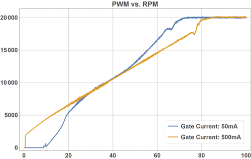
Following plots are obtained by slowly increasing the PWM duty cycle and logging the motor RPM,

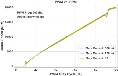
Motor behaviour at two different gate currents.

Especially the drops near the 17000 RPM region are problematic as we are operating the motor in this region.

Lowering the PWM frequency prevents this behaviour. However, as the R/L ratio of the motor is quite large (i.e. small electrical time constant), we prefer using high PWM frequencies.

Best Regards.

  • Hi Kursad,

    We will investigate and reply soon. While waiting, can you confirm you are PWM'ing at 200kHz? The plot shows 20kHz.

    If you are PWM'ing at 200kHz, what is your duty cycle?
    Have you tried changing the TDRIVEN and TDRIVEP to 880ns or 440ns? At 200kHz, there is not much time to disable one FET and enable the other.
  • Hi Rick,
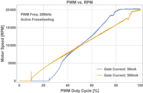
    I forgot to label the axes, vertical axis is the motor RPM and the horizontal axis is PWM duty cycle (over 100). The PWM frequency is constant and 200 kHz.
    I will change TDRIVEN and TDRIVEP values and come back.
    Best Regards.
  • Hello again,

    I've lowered the TDRIVEN and TDRIVEP values but the response is practically identical to the above plots.

    Best Regards.

  • Hi Kursad,

    Thank you for the information. We will update you soon.
  • Hi Kursad,

    I will suggest also check all the calculations which are dependent on PWM frequency such as PWM duty cycle etc.

    From waveform, it looks like when speed is ramping up to 14-Bits value (16383) then your Motor is out of control, means it’s running with maximum RPM (lost control), so there is chances that any of the control parameters  is going out of range or overflowing.

    And if motor is not drawing high current or device is not heating up then I think it should not be dead time issue.

    Thanks

    Abhishek

  • Hi Kursad,

    - At what switching frequency do you see this speed behavior improve?
    - For the 1x PWM mode on our device, do you see better speed performance using DIODE FREEWHEELING (COMM_OPTION register set to 0x0)?
  • Hello Again,

    Thanks for your replies. I've checked my PWM signal and found out that it had a positive offset previously. But the problem is not related to this. Speed drops and jumps near the 17000-18000 RPM region still exist.

    I've measured the PWM signal at the INHA pin of the DRV8305. It is ramping from 0% to 100% linearly. There aren't any problems in there.

    Here are the latest results,

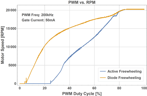
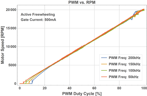
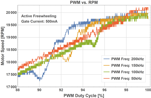
    I've tried diode freewheeling with a 200kHz PWM,

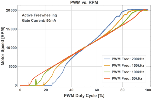
    Here are the results with different PWM frequencies,

    With 50mA gate current,

    With 500mA gate current,


    Best Regards.

  • Hey Kursad,

    Appreciate the indepth information, this is helpful in debug.

    It looks like the linearity of the speed curve in your application improves with a higher IDRIVE setting. Have you tried using either the .75 A or 1 A IDRIVE settings on the DRV8305? Do you see improvements at high speeds with stronger source / sink currents?
  • Hi Phil,

    The linearity of the curve improves with the increasing gate driving current like you said . However, after 500mA, there is not much change. Also, sudden jumps near 17000 RPM region still exist. These jumps are our main problem.

    Higher gate driving currents also introduces noise related problems in our case. We prefer using lower values.

    Best Regards.

  • Hi Kursad,

    Can you experiment one more thing and capture the waveform, When PWM duty reaches around 90 to 92 % then don’t increase PWM duty linearly, instead give 100% duty.

    If any bootstrap capacitor involved then it will not get sufficient time for charging/discharging because you are switching with very high frequency 200 kHz (5us). And above 90% duty complementary (lower side) is on only for 10 %( 0.5 us). I think this time might not be sufficient.

    Thanks

  • Hi Abhishek,

    Here, the PWM duty is changed right before the speed decrease (~88% >> 100%),

    Zoomed,

    Here, the duty is changed right before the sudden speed jump (~90% >> 100%),

    Best Regards.