This thread has been locked.

If you have a related question, please click the "Ask a related question" button in the top right corner. The newly created question will be automatically linked to this question.

DRV8303: The BLDC waveform is abnormal in case of heavy load(It seem Drv8303 weak pull down the signal about 1ms , then recover automatically )

Part Number: DRV8303
Other Parts Discussed in Thread: DRV8301
Motor : 2*250W BLDC
Drive way: 3 Hall sensors and H-PWM-L-ON;
Summer
If you find out this conference,please read this paragraph carefully.
If you find your drv830x device was reset automatically(or find the device would recover by itself) ,and you have check all the vol that is normal, you could check whether you connect the AGND and POWER PAD directly. You should connect the two pin as short as you can.
Maybe I hope the discusion below would give you more thinking direction to solve problem.
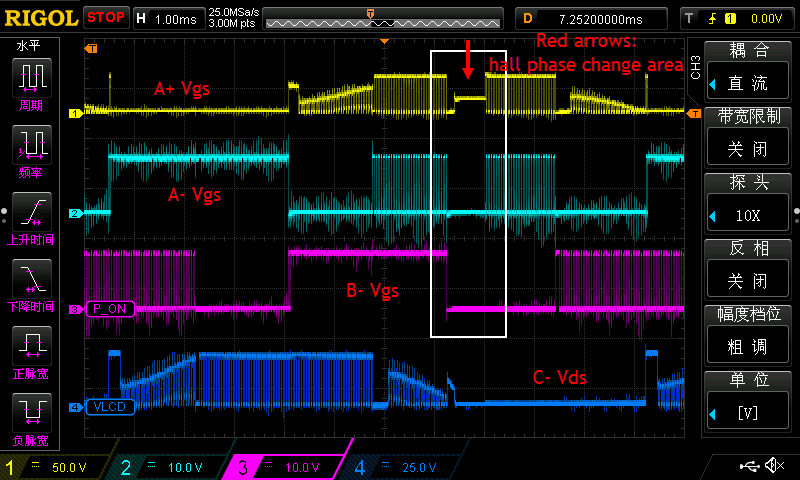
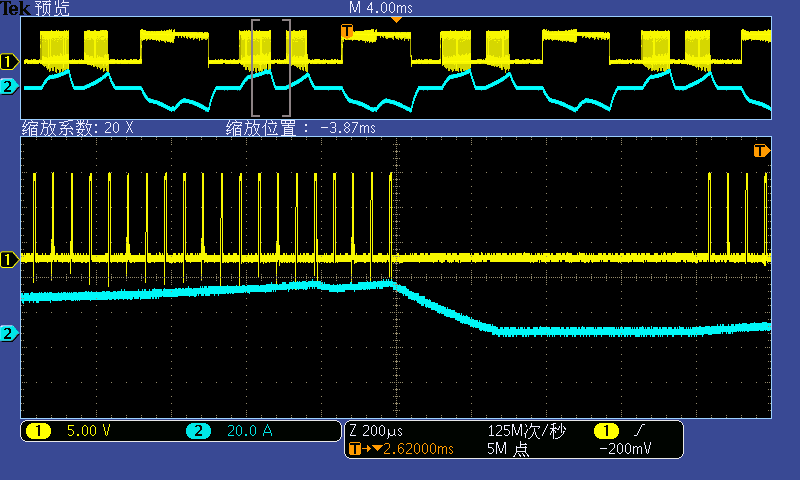
The issue is the motor running normally in case of light load, but when the load turns heavy, the motor sound big noise and the waveform is abnormal. Just like the pic below. The white rectangle indicates the question, the all gate of FET have been pulled down .However,  It should be PWM.
what I have check:
1. Fault pin report the error , in line with the area of white rectangle; At the same time ,the OCTW pin kept high; then read the status reg which is 0xff (It is weird) .
2. The PWM input between MCU - > DRV8303 is OK;
3. I have check the PVDD\DVDD\AVDD\GVDD twice and did not found any unusual;(the cap near power pin follow the pdf)
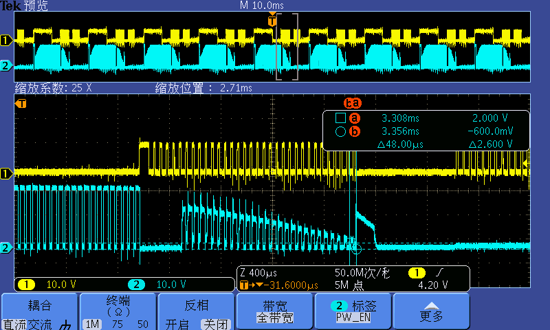
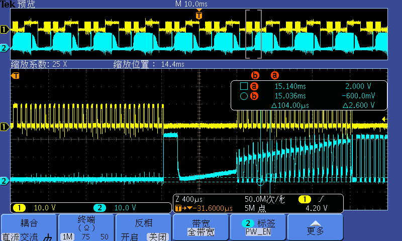
4. the C- Vds waveform may have some mistake, but I didn't know clearly;
5. When the error occurd, the phase current was about 16A. The internal resistance of FET was about 3.8mohm, the max current allows 80A.
6. It also seems EN-GATE was OK;
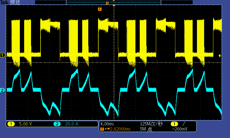
7. I have 4 PCB boards(two layout ways), every board have the same phenomenon. The left driver is almost OK, and check the waveform could see some error. The right driver is serious.
8. I have disabled the OC detect. And set the OC_Adj is 31(2.4V);
  • Part Number: DRV8303

    Motor : 2*250W BLDC
    Drive way: 3 Hall sensors and H-PWM-L-ON;
    The issue is the motor running normally in case of light load, but when the load turns heavy, the motor sound big noise and the waveform is abnormal. Just like the pic below. The white rectangle indicates the question, the all gate of FET have been pulled down .However,  It should be PWM.
    what I have check:
    1. Fault pin report the error , in line with the area of white rectangle; At the same time ,the OCTW pin kept high; then read the status reg which is 0xff (It is weird) .
    2. The PWM input between MCU - > DRV8303 is OK;
    3. I have check the PVDD\DVDD\AVDD\GVDD twice and did not found any unusual;(the cap near power pin follow the pdf)
    4. the C- Vds waveform may have some mistake, but I didn't know clearly;
    5. When the error occurd, the phase current was about 16A. The internal resistance of FET was about 3.8mohm, the max current allows 80A.
    6. It also seems EN-GATE was OK;
    7. I have 4 PCB boards(two layout ways), every board have the same phenomenon. The left driver is almost OK, and check the waveform could see some error. The right driver is serious.
    8. I have disabled the OC detect. And set the OC_Adj is 31(2.4V);
  • Hi Vander,

    For your first point you say that you've read back the STATUS register and get 0xff, which would imply that the SDO pin is not correctly clocking data out of the SPI registers.  

    Are you sure that you've correctly configured your SPI interface?  Is VDD_SPI correctly powered on?  Are you able to check the nSCS, SDI, SDO, and SCLK signals to make sure they're connected to your Microcontroller?

  • Hi Vander,

    For your 4th point

    I have highlighted the issues in the waveform with ”?”.

    Thanks

    Abhishek

  • Yes,I sure that the SPI is right. We have try to read the other reg, it's OK.

  • The yellow waveform with "?" is come from program, Only one FET open, I think it doesn't matter.
    The blue waveform with "?" which I did not know clearly.I doubt it too.
  • As per my understanding yellow and blue both are similar behavior due to programming. But in case of blue there is some other issue also which switching off your PWM drive, we will try to debug that.

    At the time of hall state change, are you switching off all the PWM (or GPIO reset) and then configuring again? If program is doing that then you will get all issue highlighted by "?".

    Thanks
  • Firstly , we did not switching off all the PWM when hall state change;
    Secondly,we use H-PWM-L-ON and !PWM to drive FET. At the other words, A+ is driven by PWM, A- is driven by !PWM, B- is driven by high vol.

    thirdly, I think the main cause is PCB layout. As our program on TI demo board is Ok. If you need PCB source file ,I could send to you.

    I also try to pull down the engate pin ,then pull up. The drv8303 still work...protect...work...protect....status register also 0xff when protecting.

    the MOTOR system is almost 300~400W(24V*16A). Is any problem may cause DRV8303 work abnormally or influent the ref. So that all the reg will turn to 0xff.
  • 1st, At the time of hall state change, we did not switch off all the PWM (or GPIO reset) and then configuring again.we use H-PWM-L-ON and !PWM to drive. at the other words, A+: PWM; A-:!PWM; B-:High vol and then switch to the next status directly.

    2cd,I think the main cause is PCB LAYOUT. As our program on TI demo board is ok. If you need PCB source file ,I can send to you.

    3st, I tried to pull down the drv8303 engate, then pull up. The phenomenon is drv8303 recover then protect...recover...protect, the motor cannot running.

    Is any reason may cause the drv8303  work abnormally or influent the ref vol. So that the status reg turn to oxff?

  • 1st, At the time of hall state change, we did not switch off all the PWM (or GPIO reset) and then configuring again.we use H-PWM-L-ON and !PWM to drive. at the other words, A+: PWM; A-:!PWM; B-:High vol and then switch to the next status directly.

    2cd,I think the main cause is PCB LAYOUT. As our program on TI demo board is ok. If you need PCB source file ,I can send to you.

    3st, I tried to pull down the drv8303 engate, then pull up. The phenomenon is drv8303 recover then protect...recover...protect, the motor cannot running.


    Is any reason may cause the drv8303 work abnormally or influent the ref vol. So that the status reg turn to oxff?
  • I check all register, and find that all registers have been set to oxff when the issue occured.
    So it may means, the mcu in the DRV8303 was disturbed. The DVDD may have some noise?

    and the AVDD\PVDD\GVDD is OK. and the ref pin is ok too.
  • the reg have been set to 0xff, then reset the default value.
  • Hey Vander,

    This may be an issue with the DRV8303 DVDD voltage moving due to unwanted ground bounce on your PCB layout. This can cause the SPI registers to be reset when DVDD drops below a certain value and would explain the 0xff in the STATUS register.

    We have an app note on the DRV8301 (same SPI map / gate driver blocks) that outlines proper layout and this behavior:

    www.ti.com/.../slva552.pdf

    I would advise monitoring your DVDD regulator in reference to ground on your PCB to see if there are any significant changes in voltage when the DRV8303 nFAULT pin is driven low.
  • Hey Phil

    Thank you for help very much. The pdf you advise is helpful for us, too.
    I finally find the reason . I tried to connect the Pin24 to Pin49(power pad), the issue have been solve.
    To my way of thinking, the PDF divides the pin24 AGND and Pin49 power pad, I think AGND and Power pad can not connect directly.
    But yesterday, I have a idea and tried to search why DRV8303 would reset automatically, and find the similar problem, then the measure is effective.

    I will edit my answer in front of this conference so that other may see the method quickly.

    the reference website:
    e2e.ti.com/.../1943657
  • Hi Vander,

    Thank you for following up with your findings.