Part Number: DRV8837EVM
Other Parts Discussed in Thread: DRV8837
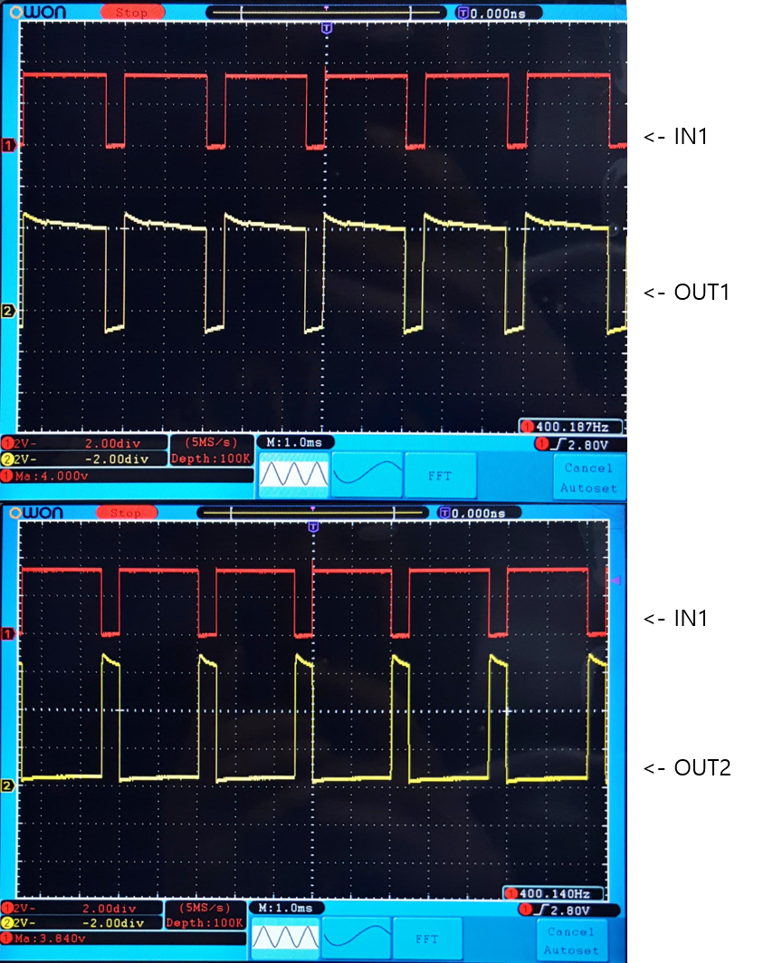
IN1 : PWM duty 80%, IN2 : PWM duty 0% / 400hz

Why is the IN2 and OUT2 different??
I think the back EMF is a problem... right?
Part Number: DRV8837EVM
Other Parts Discussed in Thread: DRV8837
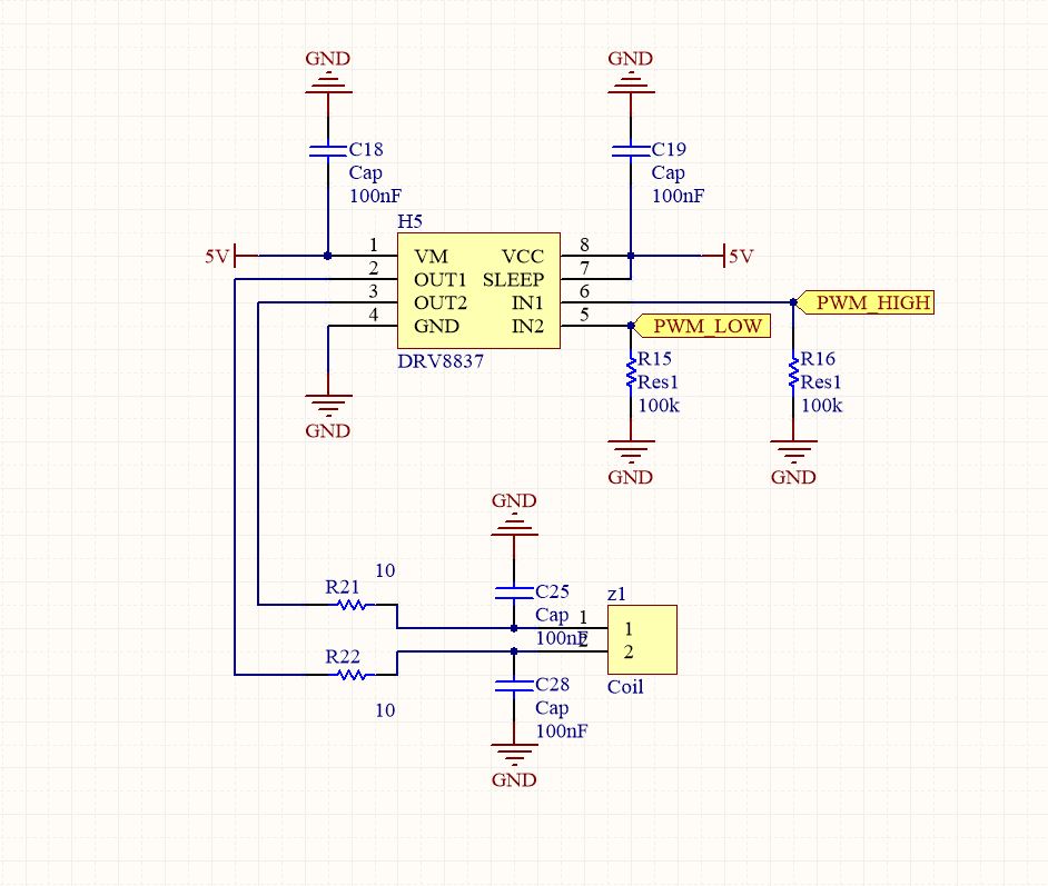
IN1 : PWM duty 80%, IN2 : PWM duty 0% / 400hz
Why is the IN2 and OUT2 different??
I think the back EMF is a problem... right?