This thread has been locked.

If you have a related question, please click the "Ask a related question" button in the top right corner. The newly created question will be automatically linked to this question.

DRV8884: DRV8884EVM problem

Part Number: DRV8884

Dears

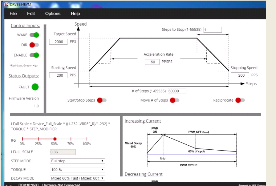
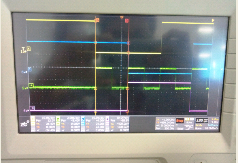
      When we used DRV8884EVM, We meet some problem need to help. when we set as below picture, we selec the start/stop steps button. we test the Step pin waveform of  the DRV8884 chip(the 2rd channel wave), we find that the wave can't change after 32ms, and after 60ms, there is also no any change . when we go on , the wave change.  So our quertion is that when the wave would chage after we select  the start/stop step button, and is there any rule ? the PPSPS vuale can affect it ?  how the ppsps control the PPS ?

  • Hi Aggil,

    Please try the following and report if the STEP input increases:
    1) Start with the GUI image above.
    2) Set Wake and Enable low
    3) Set the acceleration rate to 500 PPSPS
    4) Set Wake and Enable high --- This step recalculates the acceleration profile
    5) Select Start/Stop Steps

    The frequency of the STEP pin should begin increasing at approximately 32ms intervals.
  • Hi Rick

     Thanks ,  and there is another question need you to help. 

     If  motor current limit is 275mA, that is IFS is 275mA(the full step ), now if it sets 1/2 step, 1/4, 1/8..., how much is the current  ?  how I set the current ? How to uderstand the below table ?  Arbor number 1,2,3... stand for ? 


  • Hi Aggil,

    If motor current limit is 275mA, that is IFS is 275mA(the full step )?

    If you set motor current at 275mA, the full step current will be 71% of 275mA (195mA).
    You will reach 100% (275mA) and the 90, 180, 270, and 360 electrical degress when running microstepping.

    How to uderstand the below table ? Arbor number 1,2,3... stand for ?
    The DRV8884 contains a table that sets the percentage of full scale current per step. The table defines a 360 degree electrical rotation of the stepper motor (4 full steps) and is different for each micro step mode.
  • Hi Rick
    Sorry, I don't understand clearly. If my motor current is 275mA, meanwhile, the micro step mode is set in 1/4 step (M1=M2=1), how i design the IFS and RREF value if the TRQ =0 ?? thanks
  • Hi Aggil,

    Please refer to equation 1 of the datasheet.

    For 275mA, use the closest resistor to 109kOhm. This will provide 275mA at steps 1, 5, 9, and 13 of the indexer table.

    The RMS current will be 195mA/winding.
  • hi Rick
    thanks, So i understand the IFS is not relative with the step mode . Such as IFS is 195mA in full step mode , when i set into 1/4 step mode(the other parameters don't change ) , the IFS should also be set 195mA, is that right ?
  • Hi Aggil,

    Correct. If you set IFS to 195mA using equation 5, 195mA is the current when 100% is shown in the indexer table 2.
    For full step, the current will be 71% of 195mA or 138mA at each step.