This thread has been locked.

If you have a related question, please click the "Ask a related question" button in the top right corner. The newly created question will be automatically linked to this question.

DRV2603EVM-CT: Question for Auto-resonance tracking control method by MCU in EVM-kit

Part Number: DRV2603EVM-CT
Other Parts Discussed in Thread: DRV2603, DRV2604

Hi~ 

One of our customer requested how to set MCU in EVM for Auto-resonance tracking control.

They want to control the time for continuous operating motor and the output voltage.

Currently they have promoted and guide to use DRV2603, 2604 with their motor product.  

And one more, they want to know how to check the voltage to motor from DRV2604.

They said they had tried to check the voltage using filter circuit in datasheet but they couldn't check exact voltage.

Please check and reply soon.

Thanks in advance.

  • Hi MYUNG,

    Can you please clarify your question?
    In the above statements you mention the DRV2603 and DRV2604, but which one are you using? These two devices have very different setups and features.
    It can be difficult to measure the output voltage because the output is switching (Class-D). For our measurements, we use a LeCroy oscilloscopes and the ERes digital filter.
  • Thank you for quick reply and sorry for confusing you.

    Customer is  using DRV2604 to check their LRA motor and guided to use together.

    Today I got more information and detail of issue as below.

    1. End customer requested to check noise on LRA motor.

    2. Our customer want to know that noise was caused by over voltage to LRA motor

    3. Our customer check the vibration strength and noise their LRA motor with 2.0Vrms.

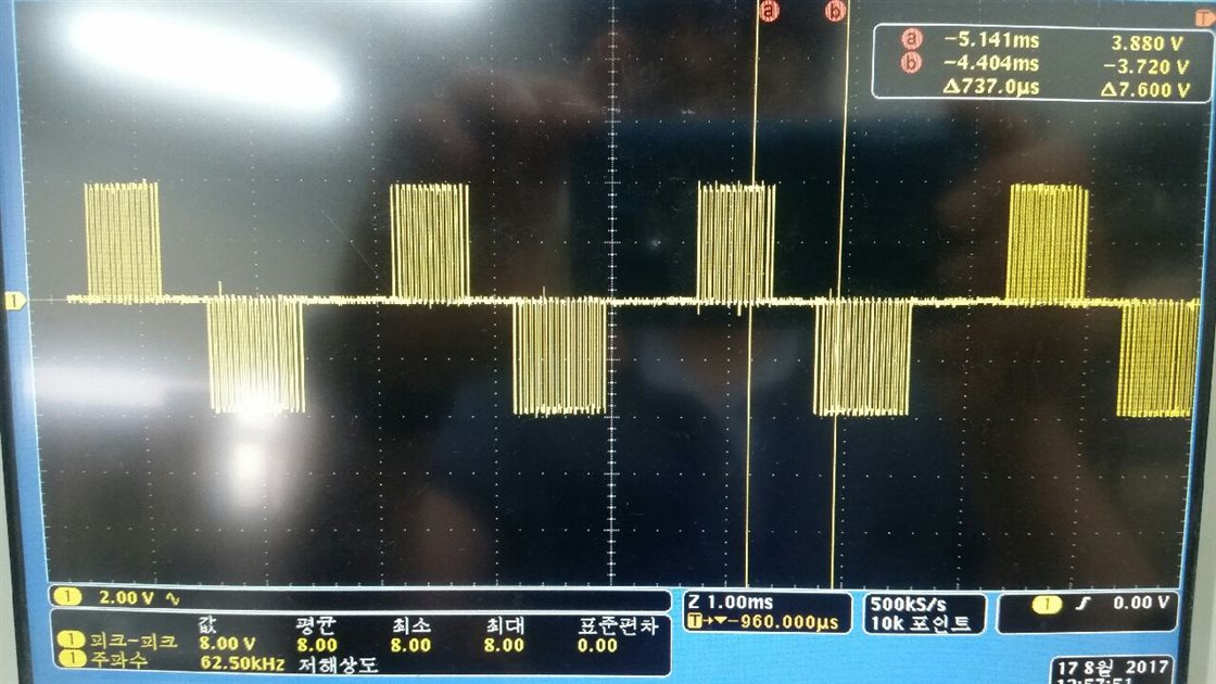
    4. After checking Out+/- to LRA motor, they have checked below result.

    5. They think that the end customer applied 4V to LRA motor based on below picture in datasheet

    Would you please check and give me your comments?

    Thanks in advnace.

    Morgan


  • Hi Morgan,

    1 & 2) If the motor is making a loud audible noise, then the rated voltage is too high. Reduce the rated voltage. You need to re-run the calibration algorithm after making changes.
    4) This looks like an unfiltered waveform. If you factor in the pulse width of the output class-D drive signals, then the applied voltage will be less than 4V.

    I recommend reducing the rated voltage and calibrating the LRA again.