This thread has been locked.

If you have a related question, please click the "Ask a related question" button in the top right corner. The newly created question will be automatically linked to this question.

DRV10983Q1EVM: Trouble at higher Duty cycles

Part Number: DRV10983Q1EVM
Other Parts Discussed in Thread: DRV10983-Q1

Hi, 

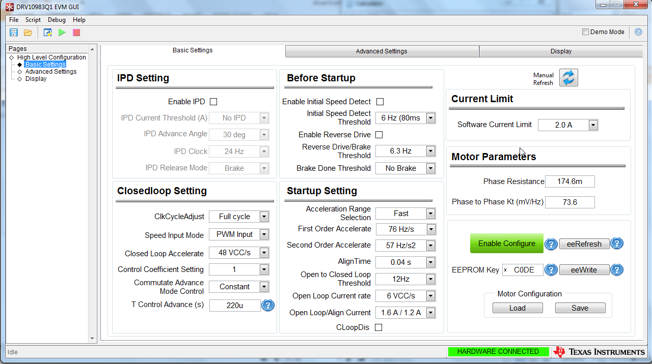
     I'm evaluating DRV10983Q1-EVM to spin a  24V 3-phase BLDC motor(model No: 57BLF03 - hyperlinked) with 8 poles. Following are key parameters I set in the GUI of the EVM software:

  • Phase resistance - 174.6 mOhm.  This value is half of the resistance between U and V phase of the BLDC I'm using.
  • Phase to Phase Kt - 73.6 mV/Hz . I calculated this value using the formula : Motor velocity constant = (VCC/Maximum motor speed(no load)) . VCC= 24V , Maximum motor speed = Max. RPM/ (60/No. of pole pairs) = 5000/(60/4) = 333.33. Now Kt = 24/333.33 = 72 mV/Hz. Closest value is 73.6 in the GUI of 10983Q1EVM

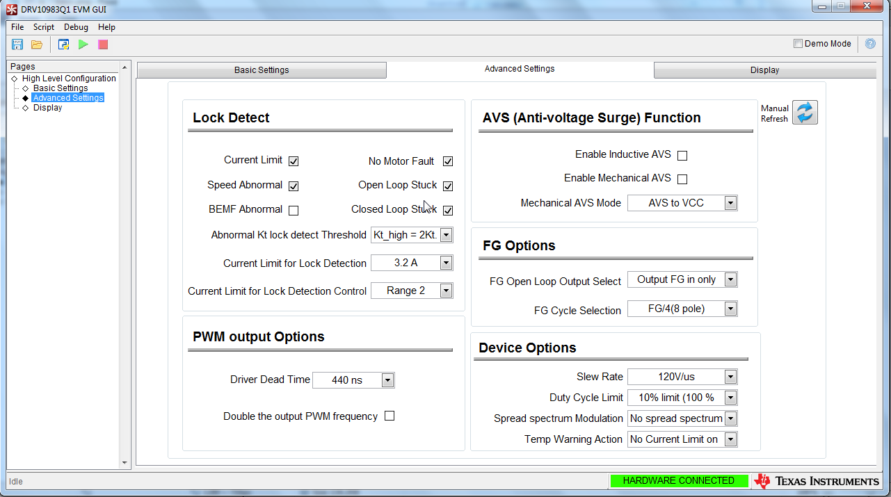
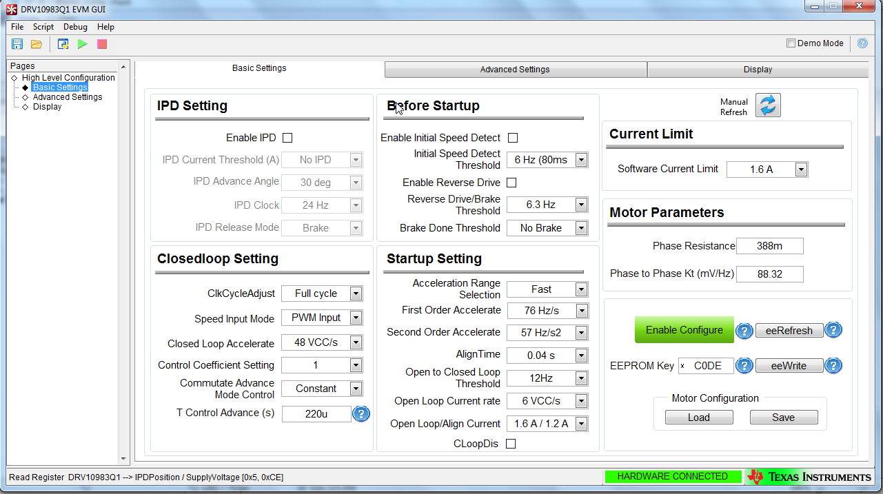
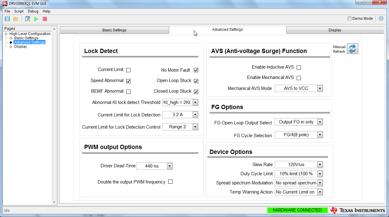
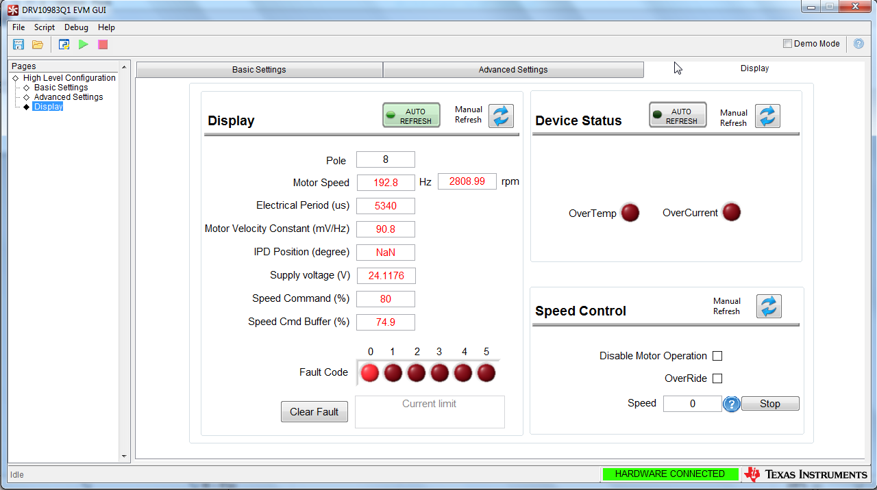
Following are the screenshots of the DRV10983Q1 EVM GUI 


These are the screenshots when I'm trying to run the motor with PWM at 30% dutycycle from my Beaglebone. As you can see in the Display tab that speed CMD buffer is not able to reach Speed Command (if my understanding is correct, motor is running at 30% duty cycle when the Speed cmd buffer is at 30%.) If I increase my PWM dutycycle to 40 or 50 or 100 , Speed cmd buffer doesn't change and the motor speed remains unchanged. When I increase the software current limit to 3.0A or disable it and start the motor, it stops after few degrees of rotation due to the Fault code- 0 i.e current limit whereas the maximum current drawn from the power supply never exceeds 0.3A.  The current limit is set to 2A on the power supply which the motor never crossed. 

Below is an image of the oscilloscope and power supply. The frequency out from the FG test point on the 10983Q1EVM is 7.088Hz(in yellow) and the input pwm frequency in Blue is 2000Hz and duty cycle is 30%. 

Kindly suggest what needs to be done to get the motor running at higher duty cycles i.e higher RPMs. Ultimately what I want to do is run PID loops on my BLDC motor with quadrature encoder which will require the motor to operate at different duty cycles ranging from(10-75) and requires fast response to accelerate the motor.


  • Hey Puneeth,

    Sounds like you could have a problem with programmed Kt value.

    I’d like to mention that Kt is a primary parameter used to drive the DRV10983-Q1 to a certain speed in closed loop. As a result, let’s make sure that verify your measured Kt value with a different method highlighted in the tuning guide.

    Take your motor and manually spin it with your fingers when the driver is turned off. In addition, probe any of the phase voltages in reference to ground. You should see an induced sinusoidal type voltage waveform (known as the Back EMF) appear on the oscilloscope. Then measure the voltage of the waveform, peak to peak, and the frequency of the waveform. Then, using the equation below, you should be able to find Kt.

    If it matches the Kt you already have, then keep the value. Otherwise use this new Kt value and plug it into the GUI and try to start to spin the motor. If this doesn’t help, try to manually increase Kt and see if the speed command buffer gets closer to the speed command entered.

    Let me know if changing Kt doesn't fix the problem.

    Hope this helps,

    -Cole

  • Hi Cole,

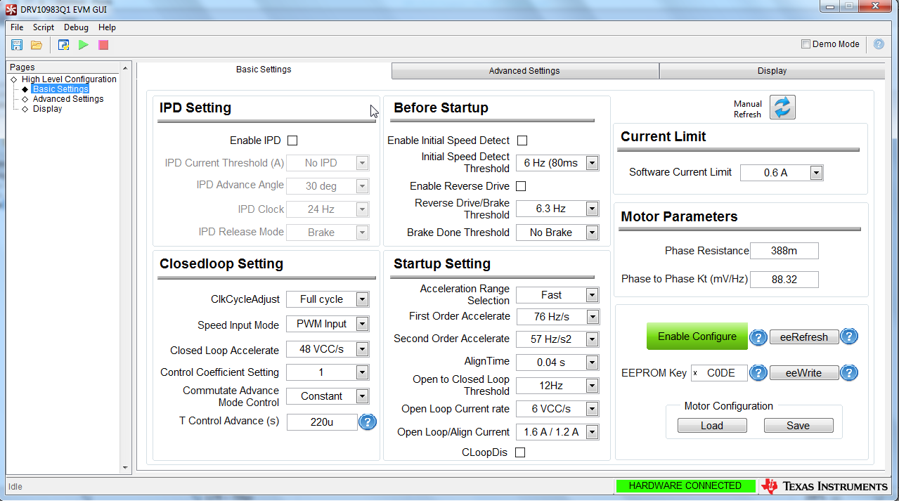
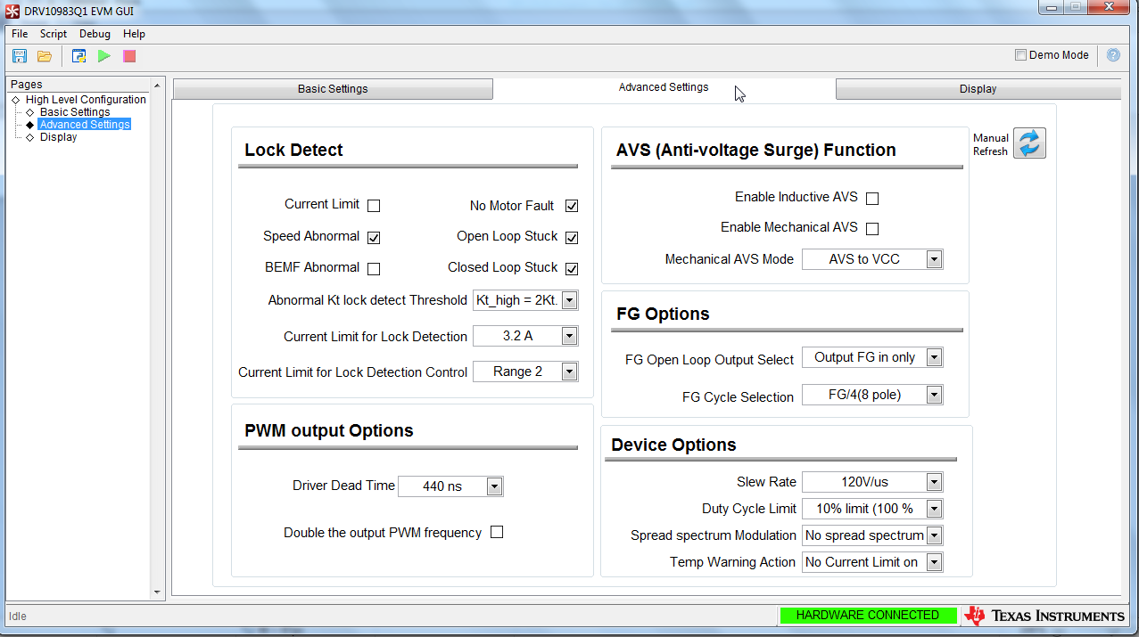
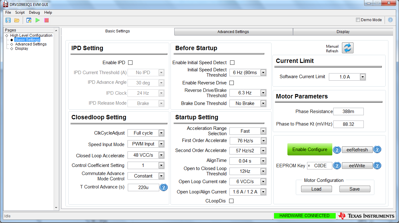
            Thanks for the reply. I calculated the Kt value according to the way you suggested and got the value as 82mV/kHz. As I increased the Kt value I found that 88mV/kHz works best. Following are my settings and results:

    Settings:

    Motor rated RPM = 3000 rpm

    Input PWM Frequency = 20KHz

    Input PWM DutyCycle = 80%

    Phase Resistance = 388m

    Phase to Phase KT = 88.32 mV/Hz

    Results:

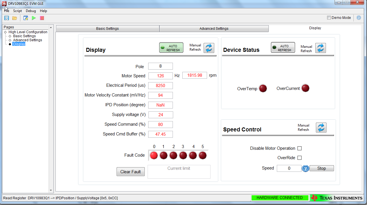
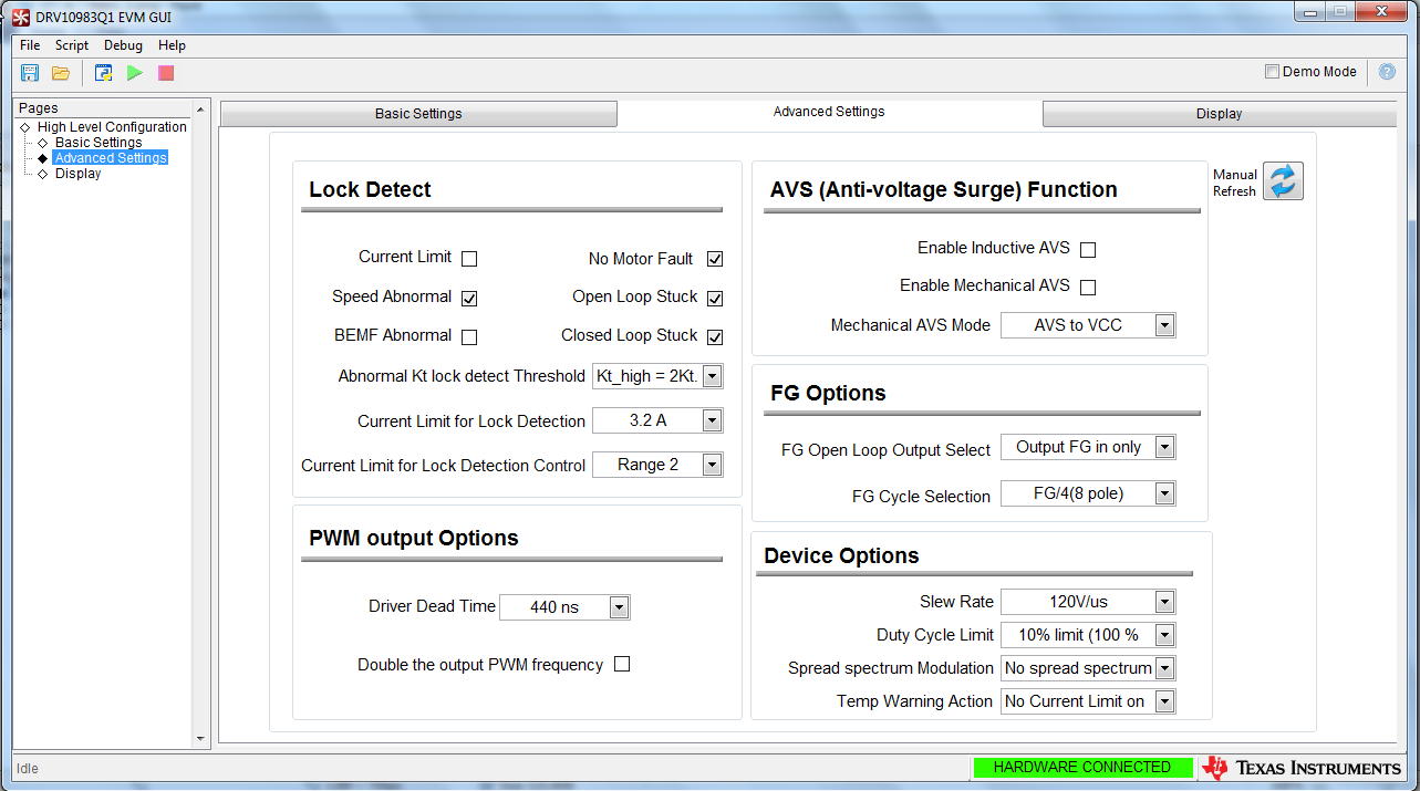
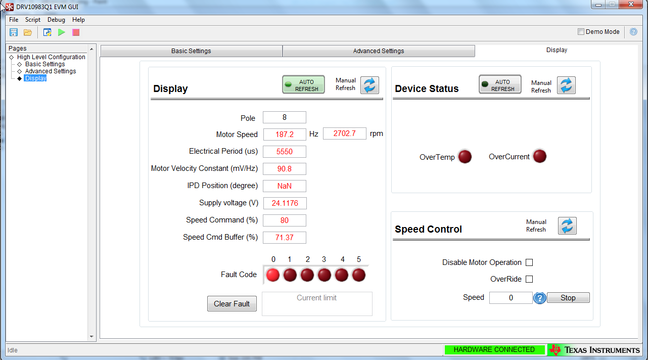
    Input PWM dutycycle for all of the below results is 80%. Screenshots are attached at the end in the same sequence given below Basic settings, Advanced , Display of respective current limits i.e 0.6A, 1A, 1.6A.

    0.6A Software Current Limit:

    Speed Cmd Buffer = 47.45% & RPM = 1815.98 rpm

    1.0A Software Current Limit :

    Started the motor with 0.6A current limit and increase it in steps of 0.2A till 1 A. The results obtained at 1A are

    Speed Cmd Buffer = 71.37% & RPM = 2702.7 rpm

    1.6A Software Current Limit :

    Started the motor with 0.6A current limit and increase it in steps of 0.2A till 1.6 A. The results obtained at 1.6A are

    Speed Cmd Buffer = 74.9% & RPM = 2808.99 rpm

    If I increase the current limit to 1.8A the motor stops showing Fault Code 2

    If I keep the current limit at 1.6A at start, the motor will rotate to some angle and stops.

    Now an ideal situation for me is  where I don't have to change the software current limit as I increase the PWM. (I'll eventually control this motor with AM437 and I don't want to use i2C frequently to change the current settings as I change PWM dutycycle). Kindly suggest a suitable solution for keeping the settings fixed and control the motor speed only with PWM dutycycle so that I don't have to use i2C dynamically to change the motor speed.

  • Hey Puneeth,

    I’m noticing a few changes between your previous settings and the settings you are showing now.

    First, your Phase Resistance now shows 388m ohms. Assuming you are using the same motor, the calculation you showed at the beginning was correct. Phase to Phase resistance was measured and then half of that should give you your Phase Resistance (176.6m).

    Software Current Limit refers to how much current can be used to change speeds in closed loop. This makes sense that you can slowly get faster as you increases the limit but as soon as it tries to go all the way, the acceleration triggers a fault and stop turning the motor. Put it up to 2.8A so the motor can accelerate to those higher speeds.

    I suggest you increase your Open to Closed Loop Threshold to at least 76.8Hz. This’ll help a smooth out the transition to closed loop. This is explained in section 4.4 in tuning guide.

    I also see you are going for a fast start up based on your align time, lets increase it 1.3s and then lower it back down when we’re done debugging. Just to be sure insufficient align time isn’t part of the problem.

    Finally we need to figure out which fault it being triggered. Remember to click the clear fault button on the display before each attempt to spin the motor otherwise the fault will not be reset. Then click the boxes for BEMF Abnormal and Current limit to re-enable them.

    If all of these setting changes are still triggering faults, report back which faults they are and then try again with slower acceleration settings and try again. Refer to Section 4.4 in the tuning guide for more information.

    Also your motor/application should have some sort of max requirements (Looks like 12A for the motor you linked). Make sure all of the current limits that are picked are below that number.

    Hopefully we get it resolved.

    Best,

    -Cole