This thread has been locked.

If you have a related question, please click the "Ask a related question" button in the top right corner. The newly created question will be automatically linked to this question.

DRV8800: nFAULT being triggered; can't figure out why?

Part Number: DRV8800

I've designed a board using DRV8800 to drive a small DC brushed motor. I first tested my circuit on a prototype board and when it seemed to work fine for the entire range of voltage that I'm going to support (8V to 24V), I got some PCBs fabricated based on the recommended layout. The only difference between the prototype and the PCB design was that I had shorted the RSENSE to GND in the prototype version but decided to use a 0.2ohm RSENSE instead for the PCB.

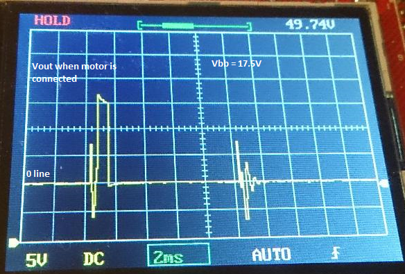
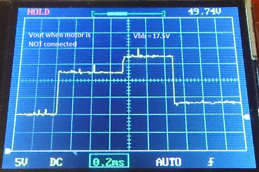
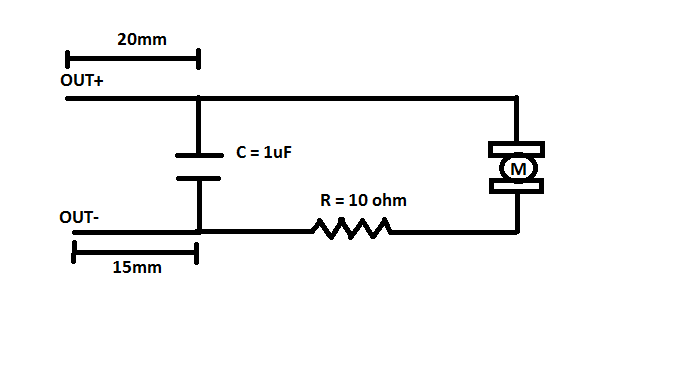
The problem I'm running into is that on PCB everything works fine up until VBB is about 15V and then it starts hitting the FAULT condition. I was able to marginally extend it to about 17.5V by shorting out the RSENSE on the PCB as well. So, essentially making it the same as the prototype and the VTRIP reads 0V. The scope reading of nFAULT shows variable downtime of about 1.5ms to 2.5ms. As another experiment, I connected a 10 ohm resistor in series with motor (R = 15 ohms) and I could get VBB to further a little more to about 18V before faulting.

I'm really stumped now that I've got several boards manufactured as well. What am I doing wrong?

I'm attaching the VOUT (with and without motor connected) and nFAULT scope output as well as the picture of the relevant section of the PCB for your reference. The board was hand soldered by me so please excuse my soldering skills.

  • Hi Peeyush,

    How well is the thermal pad connected? This may be a thermal issue.
    Do you have a second board to try?
    Can you compare the temperature of the prototype version with the fabricated board?
  • Hi RIck,

    Thank you for your reply.

    I have not connected the thermal pad yet. I have the provision of connecting the thermal pad but without any vias to the underside. My board is two sided so I did not add any vias to the underside of the thermal pad to save space on the board. It is connected to a heavy ground plane though. Would not having vias be a problem? I hand soldered my first few boards, so I found it hard to solder it and skipped it for now. I do have a few spare boards so I can try it and report back the results. I'm also getting some boards assembled so they will all come pre-soldered with thermal pad.

    I never bothered to check the temperature because when I touch it, it's hardly warm. Is it possible to overheat and still feel warm? This is my first board ever designed so I'm fairly new to the whole thing.

    Some other points worth noting:
    1. Even the prototype doesn't have the thermal pad connected.
    2. It's only the value of Vbb that seems to cause the FAULT. If I reduce it my even by 0.1V from the trip point, things run normally forever.
    3. The problem happens even with 1% duty cycle as long as Vbb is above the trip point. If Vbb is even 0.1V below the trip point, even a 100% duty cycle doesn't cause any issue. In other words, it is independent of duty cycle. I was thinking a bigger duty cycle will tend to heat things up more.
    4. The problem is present is all the boards (I have done 5 so far) with roughly the same Vbb triggering the FAULT.

    Regards,
    Peeyush Garg
  • Hi Peeyush,

    There are several potential causes of the outputs disabling.
    1) Undervoltage -- you can observe VBB dropping
    2) Overcurrent -- this is unlikely based on your description of 25 Ohms (10 Ohms series + 15 Ohms motor) and the fact nFAULT is not ~1.2ms consistently
    3) Overtemperature -- this can occur quickly if the thermal pad is not connected. The device will then cycle in and out of overtemperature. As VBB increases, the amount of current increases and creates more heat.

    Please connect the thermal pad.
  • Hi Rick,

    I've re-soldered the chip to the board with thermal pad connected this time and there isn't any difference. It's FAULTing at exactly the same Vbb as before (17.5V). I've verified that the Vbb is very stable. The datasheet mentions three more FAULT causes viz. charge pump fault, short-to-supply and short-to-ground. Can you please explain what each of these mean and could I be hitting any of them?

    Any other ideas?

    Thanks,
    Peeyush Garg
  • Hi Peeyush,

    From the datasheet:
    The VCP voltage level is internally monitored and, in the case of a fault condition, the outputs of the device are disabled.

    The VCP should be approximately 12V above VM when operating properly.

    Short to supply or ground:
    The current flowing through the high-side and low-side drivers is monitored to ensure that the motor lead is not shorted to supply or ground. If a short is detected, the full-bridge outputs are turned off, flag nFAULT is driven low, and a 1.2-ms fault timer is started.
  • Hi Duncan,

    I just prepared a new board with the thermal pad soldered and it's giving me the exact same results. I have Rsense = 0.2 ohm (no shorting) and it starts FAULTing at Vbb = 14.9V. I measured VCP and it is indeed 12V above Vbb (I tried various values for Vbb faulting or no faulting).

    What else could cause such a consistently erratic behavior?

    Regards,

    Peeyush

  • Hi Rick,

    A small update. Not sure if will help. I am using a ceramic bulk capacitance of 10uF. I tried replacing it with 10uF electrolytic but no difference was observed. However, if I increased it to 100uF, the threshold at which it falls actually became lower by 2V to 13V. So, it would now FAULT at 13V instead of 15V. So, then I thought of completely removing bulk capacitance at all just to see what happens. Guess what, the threshold voltage increased by about 1V to 16V. Now this seemed a bit contradictory to what is in the datasheet. More bulk capacitance should have helped with current stability and increasing it should have possibly bumped the threshold of FAULT voltage a little bit. What are your thoughts?

    I can't seem to figure out the issue. Anything else I can try to diagnose/debug the issue?

    Thanks,
    Peeyush Garg

  • Hi Rick,

    Further update. I have a 1uF capacitor across the OUT+ and OUT-. This works fine in my prototype test system but it seems to be causing the issues on my PCB.

    Here's what happened. I tried increasing the output capacitance (across OUT+ and OUT-) and the FAULT started happening at a lower voltage so that gave me the idea to remove it altogether and see what happens. Voila, no FAULTs and I ramped up the voltage to 24V without any issues (I didn't go any further because that is the maximum voltage I plan to use). All this was happening at about 12.5% duty cycle. To test it out further, I switched to 25% duty cycle and the DRV8800 went up in smoke. My PWM frequency is 100Hz.

    Do you know why having a capacitor across the outputs would cause any issue and trigger FUALTs?

    What might cause the chip to blow up at 24V when increasing the duty cycle especially with all the in-built protections?

    I appreciate any insight into the above issues and what approach I should take to remedy the situation.

    Thanks,
    Peeyush

  • Hi Peeyush,

    I had ruled out overcurrent because you said you had added a 10Ohm series resistor, and the fault was not consistent at ~1.2ms.

    Placing a large capacitor like a 1uF can cause overcurrent events as the voltage increases.

    Regarding the damage, it is difficult to speculate. How are you controlling the PWM inputs at 100Hz?

  • Hi Rick,

    Thank you for your reply.

    I did place a resistor temporarily to test it out but it was placed after the capacitor (see picture) so I believe it becomes immaterial whether the resistor is placed on not for the overcurrent condition. Interestingly, it works nicely in my prototype with the capacitor. The only other difference between prototype and PCB layout is that in the prototype version the capacitor is very close to the OUT+/- terminals while on the PCB it was further down the trace about 15mm from the OUT+/- pins (possibly adding some inductance there). Since it worked in my prototype, I kept the capacitor in my final schematic for the PCB for noise filtering purposes. I see two faults in my scope, one lasting ~1.5ms and the other lasting ~2.5ms (~2 X 1.2ms) and they alternate when using the capacitor and Vbb > 15V.

    As for controlling the inputs, I'm using 3.3V MCU to generate the pulses for the ENABLE pin while keeping the PHASE high or low depending on which direction I want to turn the motor. I always ramp the duty cycle about 0.4% every 200ms. So, let's say the user application requests a duty cycle of 25%, it takes appropximately 12.5s to reach that value. FAULT, MODE and SLEEP are pulled up using 10k resistors. VREG is not connected. I'm almost using the suggested PCB layout except that I have only 10uF ceramic bulk capacitance (due to space considerations) and the 1uF output capacitor which I have now removed.

    Just when I though I figured out one issue, a bigger one has popped up. I would really hate to change my PCB in lieu of another motor driver. DRV8800 meets my requirements very nicely.

    Please let me know if you need more info.

    Regards,
    Peeyush Garg

  • Hi Rick,

    Some more updates.

    1. Replacing the OUT+/OUT- SMD ceramic 1uF on my PCB with through hole multilayer ceramic does not cause any FAULTs. Using a SMD or through hole ceramic of 0.1uF does not FAULT either. The FAULTing also stops for duty cycle between 40% and 80% even for 1uF SMD on the OUT+/OUT-.

    2. Using SMD ceramic 10uF for bulk capacitance shows huge voltage spikes on my oscilloscope (see attached) as soon as I try to increase the duty cycle beyond 50%.

    3. Using 10uF electrolytic on my PCB causes very low to moderate voltage spikes (see attached). To compare, ceramic bulk would cause voltage spikes going beyond 30V for a Vbb = 15V at about 70% duty cycle while this limit is crossed for electrolytic bulk only when Vbb = 24V at a duty cycle of almost 90%. I haven't tried again but maybe these voltage spikes are big enough to cause the motor driver failure when using SMD ceramic for bulk at a Vbb = 24V.

    4. A 100uF electrolytic bulk produces nice square waves at any voltage (no voltage spikes).

    To summarize, if I replace the two capacitors on my PCB with the ones as in my prototype board, I get the exact same results.

    What is the possible explanation for the above observations?

    I can replace OUT+/OUT- 1uF SMD ceramic with 0.1uF instead. As for the bulk capacitance, what possible alternatives exist to save space. I tried adding low value (2 ohm) series resistance to the SMD bulk to simulate ESR but it doesn't seem to help.

    Regards,
    Peeyush Garg