This thread has been locked.

If you have a related question, please click the "Ask a related question" button in the top right corner. The newly created question will be automatically linked to this question.

DRV2700EVM: DRV2700EVM Waveform issue.

Part Number: DRV2700EVM
Other Parts Discussed in Thread: DRV2700,

DRV2700 EVM Output circuit as follows:

My set up as follows:

  1. Gain: 28dB
  2. Output voltage set up :23 V 50 kΩ/  JP2 Open /JP3 Open /JP4 Open
  3. fs:2.5KHz.
  4. Duty: 50%

Test wavefrom as follows:(no load): CH2:OUT1 CH3: OUT2  

my question:

The noise for output waveform causes the buzzer to produce a different sound during the on time.

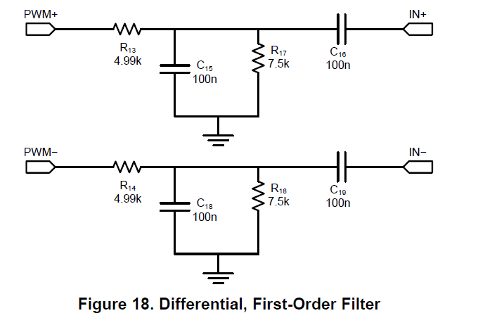
Whether the output waveform can be modified by modifying the filter. The circuit as follows,Or there are other ways to solve.

  • Hi Hsu,

    I moved your post to the Haptic forum.

    Best regards,
    -Ivan Salazar
    Audio Applications Engineer - Low Power Audio & Actuators
  • Hey Hsu, 

    Are you controlling the DRV2700EVM with Piezo Control Console with your input signal coming from the PWM of the MSP430? Or do you have an external analog input? An external analog input bypasses the input filter on the EVM. 

    The input filter on the EVM is actually the filter shown in section 8.2.2 of the User Guide. 

    The current filter has an attenuation of about -22 dB at 2.5 kHz (by looking at figure 21). If you use the filter you suggest in figure 18, that still has an attenuation of around -18 dB at 2.5 kHz, so that will help but you could consider modifying the filter even more and have the corner frequency be closer to 2.5 kHz. Modifying the input filter will change the output waveform. 

  • The pwm to the original MSP430.
    How the filter should be modified (in 2.5kHz, duty 50%)
  • Hey Hsu,

    What is the load you are driving? 

  • Hey Brouwer,
    No laod,
    The customer expect to use SMA-21(buzzer) as a load.
  • Hello,

    If you change the two 3.3k resistors to 1k then the corner frequency will be closer to 3.3kHz. But after further consideration, the noise probably originates from the single ended output implementation rather than the input filter. If you use the differential output configuration as shown below in figure 14, then the output signal should be less noisy. 

    Hope that helps!

  • My client wants to get 2 phase signal (The phase difference is 180 degrees)
  • Hi Hsu,

    The hysteretic boost converter uses a self-oscillating circuit. This means there will be some ripple voltage on the boost voltage rail that will be coupled to the outputs. If you use the differential outputs, the ripple is cancelled. If you use the single ended output structure, you can do a few things to decrease the ripple, but there will always be some ripple voltage.
    In order to decrease the ripple, you can add capacitance on the output (your load should add capacitance) or you could add additional capacitance on the boost voltage rail (BST pin). Adding capacitance on the boost voltage rail will increase the startup time because it will take longer to charge the BST cap.