This thread has been locked.

If you have a related question, please click the "Ask a related question" button in the top right corner. The newly created question will be automatically linked to this question.

DRV10983Q1EVM: Analog and PWM speed control not working

Part Number: DRV10983Q1EVM
Other Parts Discussed in Thread: DRV10983-Q1

Dear TI support team,

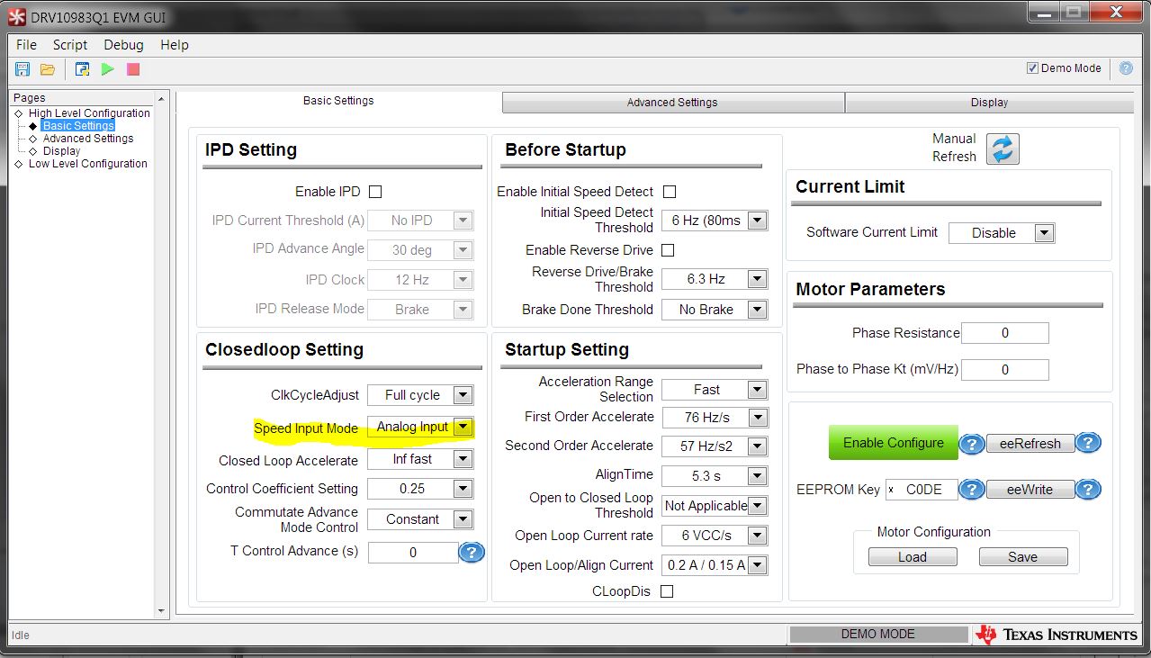
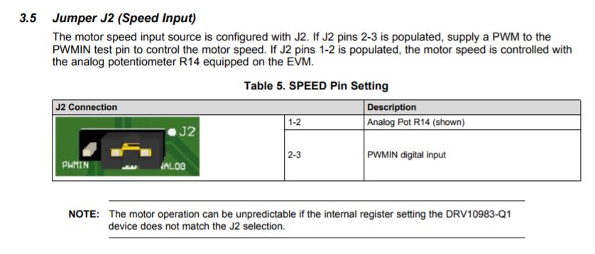
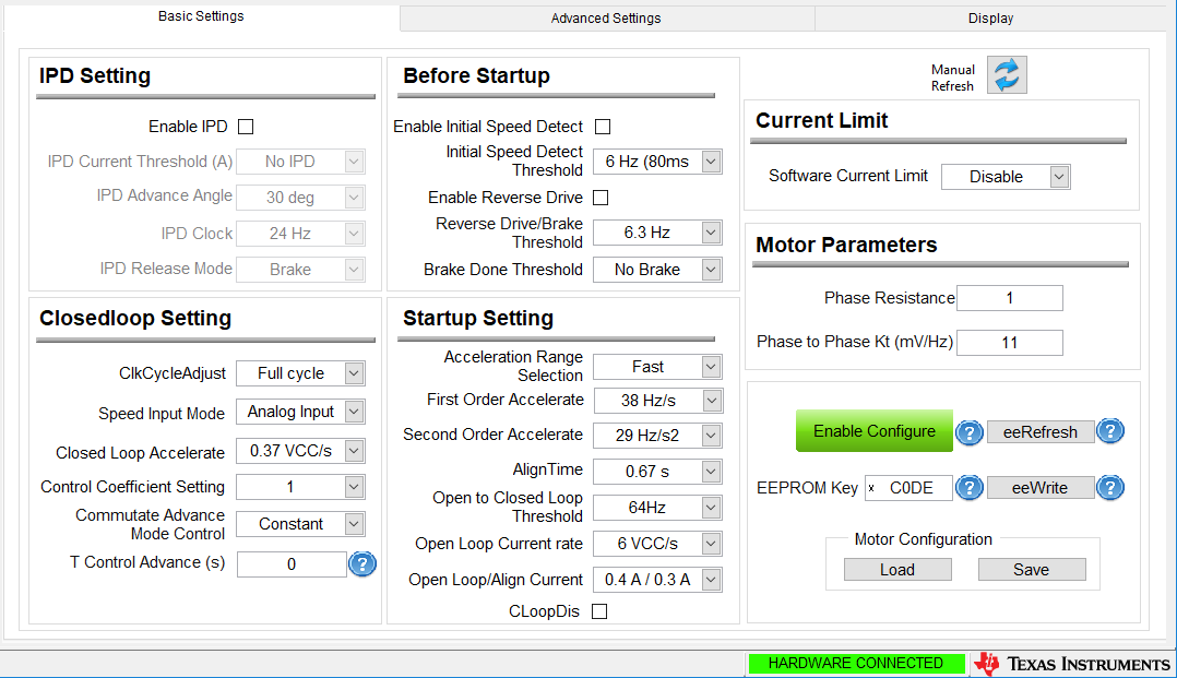
I have somes problems regarding the speed control via analog pot or pwm. I'm using the DRV10983Q1EVM to control the ec motor of a small fuel pump. 
Speed control via I2C is working fine. But when I want to control the speed via the analog pot no matter which position the pot is in the ec motor rotates with a constant speed of ca. 3600 rpm.

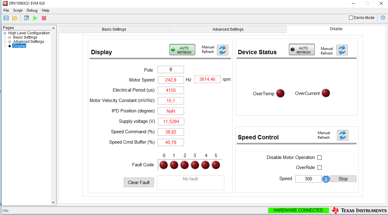
when i check the OverRide box, I'm able to control the speed via I2C. This works perfectly fine. If I stop the motor here and discheck the OverRide box the ec motor doesn't start up again. Display looks the following:

As you can see the speed demand is roughly about 40 percent, but there is no voltage supply even though the power supply is still working. 

To sum up: If the EVM is in analog speed control the ec motor spins with a constant frequency despite the analog pot voltage. (I measured the voltage of the pot and it works fine. ca. 3.3V at maximum)

This whole problem occured after I used the EVM with pwm speed control. First it worked fine. Then I changed the pwm source and it stopped working. Since then I have the aboved mentioned problems.

Hope you can be of some assit.

Regards

Alexander

  • Hey Alexander,

    If I2C runs the motor just fine, then that means there is some problem in selecting analog vs. PWM for the speed control or taking in voltage on the speed pin. There are two places to check this: the software (EEPROM settings) and hardware (J2 on EVM).

    For the software, the DRV10983-Q1 determines the speed input using the speed input mode on the basic settings tab in the closed loop setting section of the GUI. Change the drop down, click manual refresh to ensure the writes worked, and verify the option changed. I've attached a picture below where to change the setting:

    For the hardware, the DRV10983-Q1 EVM takes the voltage or PWM into the speed pin. There is a 3 pin header that goes to a potentiometer (that you've mentioned) and a PWM test point (that it sounds like you've used as well). Go to J2 and make sure the shunt is covering pins 1 and 2 of the header then turn the pot clockwise to apply the voltage to the speed pin.

    If you are having problems after testing these. Put a PWM signal on the test point and see if the device is able to take in the voltage, and monitor the voltage on the speed pin itself.

    Hope this helps,

    -Cole

  • Hey Cole,

    thanks for your help. But I already applied those changes before consulting you. The jumper J2 is so connected that the speed input from the analog pot is used. I can also measure a voltage depending on the position of the pot at the speed pin. See below my software settings for the analog speed control:

    Afterwards I also clicked on eeRefresh to see if the changes had been applied. After clicking on eeRefresh the Enable Configure button changed to red, but the speed input mode is still analog input. So I assume the modifications were saved to the EEPROM.

    Same with the PWM signal.

    The difference between the two modes is, that in analog mode no matter where the pot is positioned the speed is constant at about 3600 rpm (243 Hz). In PWM Mode the motor doesn't turn at all.
    I'm worried that the EVM IC got some damage during my testing of the PWM speed control.
    Can you advise me on some tests I can conduct to check if there is some damage?

    Regards 
    Alex

  • Another thing I observed was, that when the motor is not turning. The EVM still consumes a 60 mA current. This didn't happend before the first PWM testing.

    Thanks again for your help.

    Regards
    Alex

  • Hey Alex,

    Thanks for being patient; I thought I’d start with the basics then move from there. Please correct me if I’m wrong but I’m going to try to summarize what has happened so far:

    • Started in analog mode, turned pot some amount, observed open to closed loop behavior, was able to change pot position and change speed accordingly

    • Switched to PWM mode by changing the option in GUI, changed shunt position on J2, applied a 0 to 3.3V (digital) signal on PWM test point with some frequency between 0.1kHz and 100kHz with some duty cycle %. Observed open to closed loop behavior but didn’t change duty cycle to change speed in closed loop

    • Tried to switch back to Analog by changing option in GUI and the write succeeded (verified with refresh). Changed Shunt position as well. Turning the pot to some position results in open to closed loop behavior but speed only goes 3600 rpm while changing pot position does not change speed while in closed loop. The motor continues at 3600 rpm until turned off

    • Went to I2C mode where speed can be controlled by selecting the OverRide bit and changing 0-511 value on display tab. Observed open to closed loop behavior and changing speed value will change the rpm

    If the description above is a good assumption, then let’s try out the PWM mode again. I would like you to put the device in I2C mode again (OverRide), insert some speed command, and then change the speed mode to PWM. Refresh the registers to see if the button has stayed green and the option has changed. Then, change the shunt position and reapply the PWM to the testpoint after disabling I2C.

    The reason we’re doing writes this way is that the 983Q1 is a sleep mode device that will shut down I2C communication when there’s no voltage on the speed pin. Most often, users will try to change the setting when the device is in sleep mode which will not work.

    At the moment, it seems unlikely that the device was damaged the assumptions above are true—feel free to describe more of you previous set up. However, I’m inclined to think there’s some reading and writing troubles with the GUI.

    Also, use the manual refresh instead of the eeRefresh to read the registers. Manual refresh technically reads more registers.

    Best,

    -Cole

  • Hey Cole,

    thanks for your help very much appreciated! Your summary was almost correct
    In the first try with PWM I changed the duty cycle and the speed changed as well. Then I changed the pwm signal generator and it didn't work anymore. I did some research on my side and I discovered that the voltage of the second pwm generator was to high (up to 12 V). So I think the pin is destroyed.. my bad.. Do you agree with me on that?
    Anyway I will try to implement your suggestions I see what happens. 

    Thanks for your help anyway!

    Best,
    Alex

  • Hey Alex,

    Thought I'd close out the thread. Yes, I agree that inputing a PWM signal up to 12V on the speed pin would damage the part.

    Best,
    -Cole
  • Thanks again for your help Cole!