A related question is a question created from another question. When the related question is created, it will be automatically linked to the original question.
If you have a related question, please click the "Ask a related question" button in the top right corner. The newly created question will be automatically linked to this question.
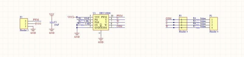
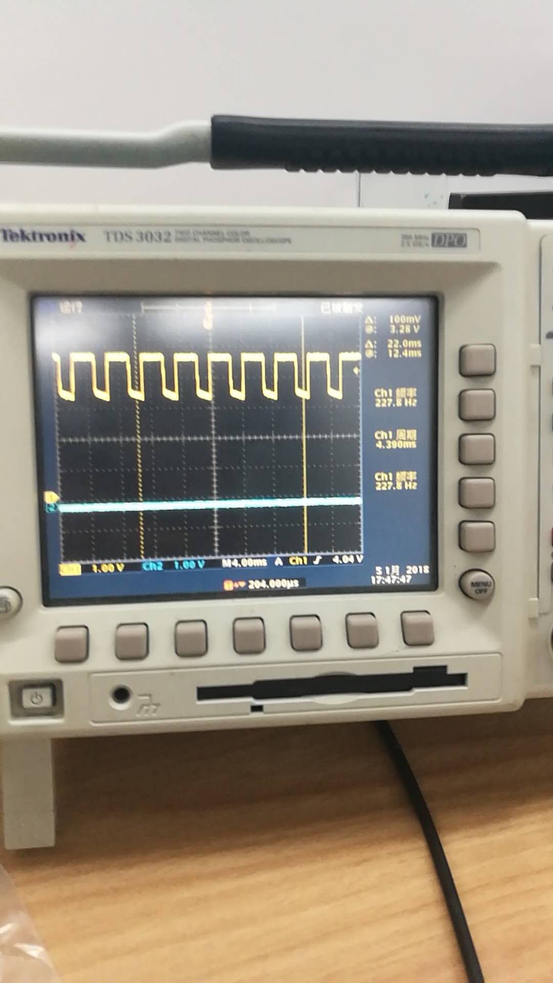
Is channel 1 the PWM input signal? If so it needs to switch from 0 to 2.3+ V. It looks like it switching from ~3.3 to 4.8V. Also, the frequency of the PWM input needs to be between 15 and 50 kHz. I'm seeing 227 Hz.
Can you show scope with Phase U current, PWM input and FG output?