This thread has been locked.

If you have a related question, please click the "Ask a related question" button in the top right corner. The newly created question will be automatically linked to this question.

DRV2605EVM-CT: Verify some information for DRV2605EVM-CT

Part Number: DRV2605EVM-CT
Other Parts Discussed in Thread: DRV2605, DRV-ACC16-EVM

Hi team,

The customer uses DRV2605EVM-CT. Now he has some questions to verify as below:

Q1. For the Figure 23. DRV2605 Unfiltered Waveform of the User Guide, how to measure the acclerometer waveform

through using the DRV2605EVM? I cannot find the  acclerometer pin in the DRV2605EVM.

Q2. 


In this document, the customer would like to get how to measure the response time and vibration strength which the two parameters

are mentioned in this document.

Q3.      

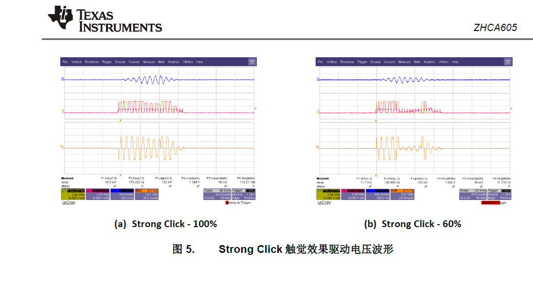
This is a Chinese version document, because I cannot find the English document. On page 13 of this document, the customer 

would like to get if  the quality of the mass is different, then the figure 5 waveform will be different. Please check the below attach 

for the figure 5.

  • Hi Mickey,

    1. The acceleration is measured using the DRV-ACC16-EVM.
    2. The response time is measured from when the GO signal is issued to when the outputs start driving a signal. This can be measured by monitoring the I2C lines and the outputs. The vibration strength is measured by the accelerometer mentioned in #1.
    3. The acceleration is affected by the mass, yes. This relates to physics, F=m*a, or force equal mass time acceleration. The force from the LRA will be consistent based on the type of LRA. Therefore if the mass increases, the acceleration will decrease. The waveform will still be the same length.
  • Hi Kelly,

    Thanks for your help. I also some questions as below.

    Q1. The customer needs to measure the Figure 23 waveform of the EVM user guide,

    then he needs to use DRV-ACC16-EVM to measure the acceleration waveform and use DRV2605EVM-CT
    to measure the (OUT+ - OUT- ) waveform and the input signal waveform. The input signal is input to the IN/TRIG pin.

    Is my understanding correct? Or how to measure the Figure 23 waveform of the EVM user guide?

    Q2. What is the GO signal that you said?

    Q3. For the figure 5 of the zhca605 document which is shown above, if the customer uses different LRA,

    then figure 5 waveform will be different?
  • Hi Mickey,

    Q1. This input signal is coming from the TRIG pin. The device is operation in closed-loop RTP mode with the trigger set to level trigger mode. The Green line is the TRIG pin. The Blue line is from the DRV-ACC16-EVM; this EVM has 3 axis so you need to select the right axis. The user guide has details. The output from the DRV-ACC16-EVM is AC coupled and filtered on our oscilloscope. The Orange line is the math function of (OUT+) - (OUT-) measured on the outputs of the DRV2605.

    Q2. You can read about the operation of the GO bit in 7.4.3 of the DRV2605 datasheet.

    Q3. The waveform will be the same, but the acceleration magnitude will change based on the LRA, the mass, and how you mount the accelerometer.