This thread has been locked.

If you have a related question, please click the "Ask a related question" button in the top right corner. The newly created question will be automatically linked to this question.

drv8320: Operation of sensored softwere

Guru 16770 points
Part Number: DRV8320

Hi

I'm evaluating DRV8320H using BOOSTXLDRV8320H EVM.

The requirement is sensored application, so I followed the user guide, the sensored project was built and loaded to device. 

I believe there is no problem up to this point.

However, I could not start motor in BOOSTXL-DRV832x GUI.

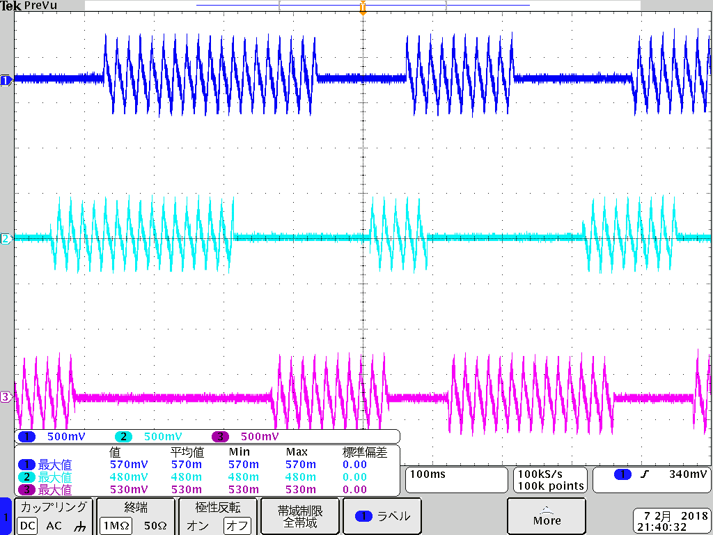
I got the following status.

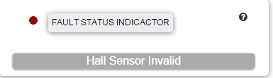
Regarding to status of LED1 and LED2 on MSP430F5529LP board, LED1 is "toggle", LED1 is "on".

The other configuration is below.

Before this evaluation, I populated R35, R36 and R38 with 0ohm for PWM inputs.

And I set 1x PWM Mode in the GUI, and start motor driving.

The tool version is below.

GUI : v1.0.0 (3fb7e5)

CCS : version 7.4.0

Motor: TelcoMotion DT4260-24-055-04H-TI

As a side note, a sensorless software worked properly with same motor.

Can you see the reason why my sensored software is not worked?

BestRegards

  • Hello na na78,

    Since you are able to use the BOOSTXL-DRV8320H EVM to spin the motor with the sensorless configuration, I'm wondering if there is an issue with the Hall sensor connections. Are the power and ground pins for the Hall sensors connected properly? Can you check the hall signals to make sure they are working? I usually do this by powering the Halls, spinning the rotor with my fingers, and looking at the Hall outputs. If they are toggling, then they are working.

    Another thought I have is about the firmware. The DRV832xx Sensored Software User's Guide says that you need to modify some parameters in Code Composer for sensored operation. Have you done that?

  • I see that you did upload the firmware with the modifications for sensored operation. I missed that part earlier.
  • Hi James

    Thank you for your reply.

    Regarding to hall IC, I will check it.

    Regarding to firmware, I did not modify it in CCS.  I used default.

    Should it be modified in CCS?

    I attached header file below.  Could you please point it out if there is any problem?

    TrapSensored_Parameters_Setup.h

    BestRegards

  • Hi James

    The VCC of hall IC would be provided from the board, but it will be 3.3V.

    If larger VCC is required to hall IC to be used, it should be provided from other supply.

    Is my understand correct?

    By the way, I got the following hall signal from powering hall IC of motor, with spinning by finger.

    Do you think this output of hall is IC correct?  

    BestRegards

  • Hello na na78,

    I think you are using the correct header file, so things should be fine from a software side.

    However, those Hall outputs do not look correct. The Hall signals that the DRV8320EVM expects should be clean on/off logic signals between 0 V and 3.3 V.

    Check the datasheet for the motor or Halls to see what supply voltage the Halls need. You are correct, they may need a higher voltage supply. Double check that the sensor outputs are open drain. If they are, then you can connect them directly to the EVM because the EVM has pull-up resistors to 3.3 V.
  • Hi James

    The hall IC seems to be broken.
    I changed other motor and the sensered software worked well.

    Let me close this thread.
    I appreciate your help.

    BestRegards