This thread has been locked.

If you have a related question, please click the "Ask a related question" button in the top right corner. The newly created question will be automatically linked to this question.

BOOSTXL-DRV8305EVM: doesn't work at low duty cycles

Part Number: BOOSTXL-DRV8305EVM
Other Parts Discussed in Thread: DRV8305

Dear all

I am using an BOOSTXL-DRV8305EVM-Evaluation board together with a Particle Photon, 120 MHz-Microcontroller (3.3V).

I configured the DRV8305 via SPI to 3-PWM-Mode in a open loop mode. For that, I give out a three sine PWM signals generated from a lookup table. PWM frequency: 28 kHz; Resolution 11 bit.

PVDD is 15V, the motor has an internal resistance of 0.3 Ohm.

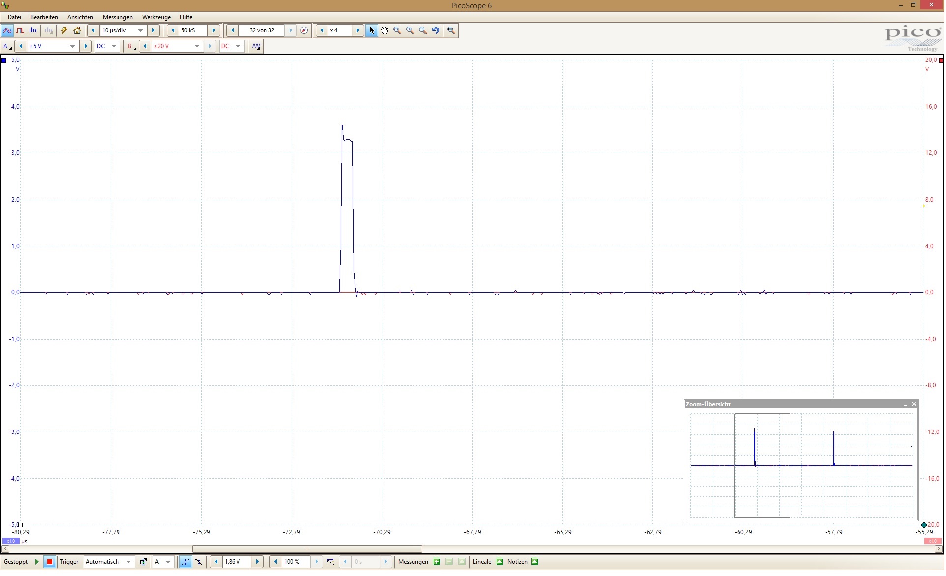
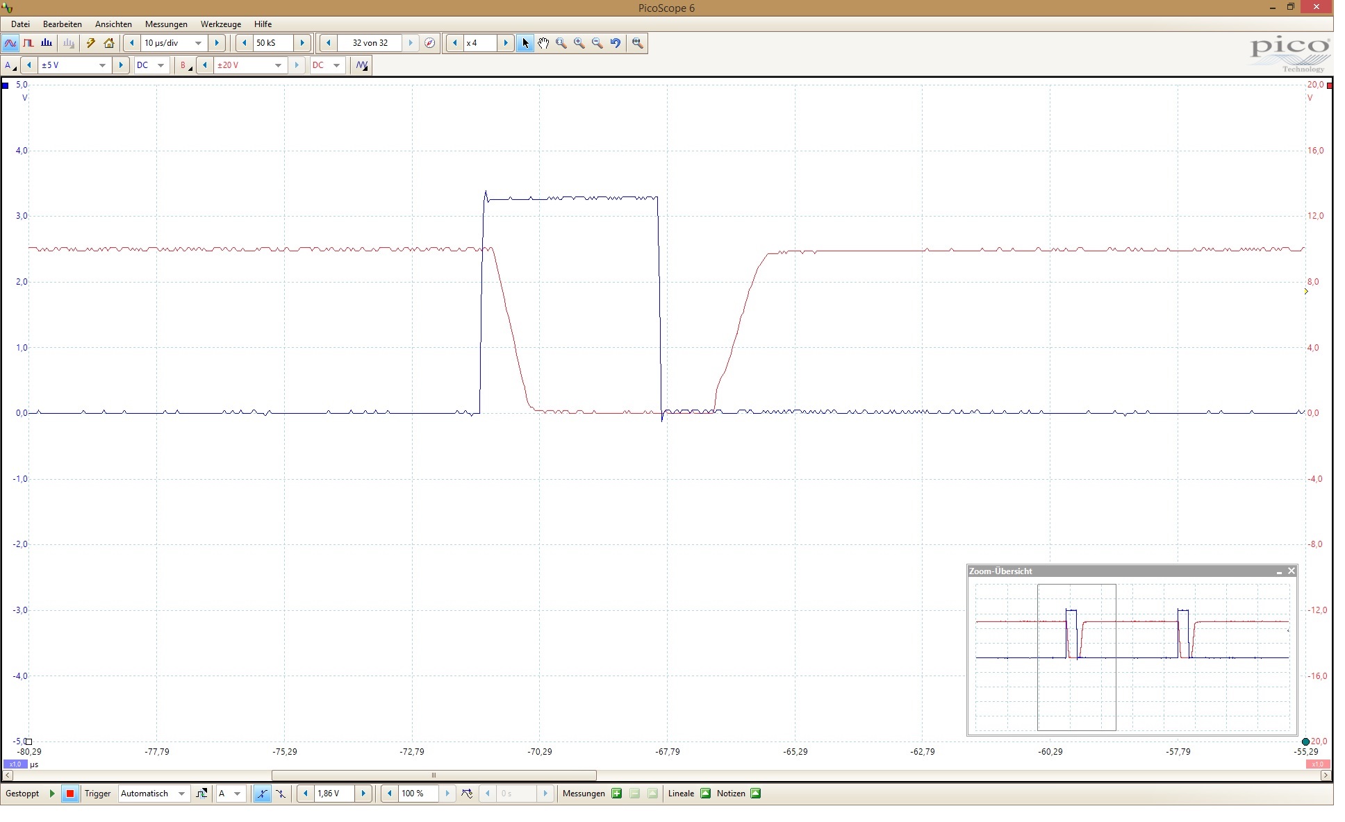
As long as the duty cyle is high enough (appr. >10%), everything seems to work well. I can measure rising and falling Voltages from every Phase to ground. But I need a duty cycle of <1% that the motor doesn't burn at free wheeling at slow speeds (1 rpm). But with a duty cycle <10%, there are no voltages applied to the motor phases. Voltages from Phases to ground stays 0V. Either there is no error indicatet (red led on BOSSTXL isn't switched on).

What is the problem? Do I have to modify some configuration values?

Thanks a lot for your help.

Kind regards

Silvan

M.Sc.

  • Hi Silvan,

    Would you please provide your register settings?
  • Hi Rick

    The only register i changed is register 0x7. If I read out the register for the MSB  i receife 0x02 and  the  LSB is 0x96. So it did what i wanted, only to change the PWM Mode from default to 3-PWM-Mode and everything else is default.

  • Nowone has an idea? Or can please commit his configuration code?

  • Hi Silvan,

    Could you take oscilloscope captures of the INHA, GHA, and GLB pins when the duty cycle is <10%? I'd like to get a better idea of what the input looks like, and see if the output stage is switching at all.

    Thanks,
    Garrett
  • Dear Garrett

    Thanks for your question.

    Attached the requested Pictures. As you can see, at 10% duty cycle everything is ok.

    With 1% duty cycle, GLA is not completly pulled low. GHA is Zero all the time.

    If I see the flat ramp at GLA (10%) and the expected begining of it at GLA (1%), it seams not to discarge fast enough. What do you mean?

    Another question, which doesn't matter with that Problem but which I asked me: Must all 3 INHx have the rising flank at exact the same time? My timers has only 2 pwm Outputs. So for 3 PWMs, I have to use 2 timers which are not synchronized. Is that a Problem? (see last Picture of INHA + INHB)

    INHA + GLA: 1% duty

    INHA + GHA: 1% duty

    INHA + GHA: 10% duty

    INHA + GLA: 10% duty

    INHA + INHB: 10% duty

  • Hi Silvan,

    The DRV8305 features internal handshaking when switching from the low-side to the high-side that is designed to prevent both FETs from turning on at the same time, causing shoot-through.

    When your input switches from low to high, the low side gate driver first applies the IDRIVEN_LS pulldown current for the TDRIVEN period. Once that time has expired, the device will wait for the internal dead time (programmable via SPI as well), and then apply the IDRIVEP_HS current for the TDRIVEP period to the high side FET. If the FET fails to charge/discharge adequately by the end of the TDRIVEN/P period, this will trigger a VGS fault, and the gate drive outputs will disable.

    As you've left most of your device configuration at the power-up defaults, your TDRIVE periods are set to 1780ns, and your internal dead time is set to 52ns. From the scope captures, at 1% duty cycle, it looks like your on time is somewhere around 1500ns, so this is why the high side never even begins to turn on.

    In order to switch at the low duty cycles that you're interested in, you'll need to decrease your TDRIVE settings, but as you can tell from the low turn on/off of the FETs in the scope captures, you'll need to increase your IDRIVE strengths as well. If you're not concerned about noise at this point in time, you can probably just set these to their highest settings for now.

    Regarding your second question: At the relatively low PWM speed you're using, I don't think the non-synchronized timers should be too big of an issue. Could you clarify if the INHA and INHB waveforms in the last scope capture are supposed to be synchronized, or is the offset between the two normal for the commutation profile?

    Thanks,
    Garrett
  • Dear Garrett

    Thanks a lot for your detailes answer. With that and reading again the manual, i think i understand now better how it works. And i will try to change idrive and tdrive.

    The only thing which could be a problem is the following: if i cummulate, according to figure 11 on page 23, 2x the minimal tdriveHS (220ns)  and 2x minimal tdriveLs (220ns), i get 4x220=880ns which is the lowest possible high time. Is that right? If it is, i like to ask if there is a solution for that:

    My pwm frequency is 24khz to be unaudible. The duty cycle resolution is 11 bit = 2048. Like this, the minimal possible high time is 1/24000/2048= 20ns. This is much shorter than the 880ns from above. What do you think? My commutation profile must be a sinusoidal one with minimum 10 steps at minimal amplitude. So from 1-10 from 2048. So now you see why i need a duty cycle of 0.1%

    The other question about timer is now clear for me. The timers have to be synchronous. On the last picture, you see the timer differences between inha-timer and inhb-timer. I will fix this, that all 3 inhx start at the same time.

    Thanks a lot

    Silvan

  • Hi Silvan,

    I've constructed a timing chart that incorporates all of the different timers in the DRV8305's handshaking procedure. Please see it below:

    When in 3xPWM mode, before the high side will begin to turn on, the DRV8305 must wait for the tDRIVEN period for the low side, the td_min minimum dead time (280ns, as per the datasheet), and the tdtp programmable dead time. After all three of these have passed, the tDRIVEP period for the high side will start.With the minimum settings for tdtp (35ns) and tdrive (220ns), this comes out to a typical value of 535ns.

    However, If the input goes low during the tDRIVEP period, the remainder of the period will be skipped, and the tDRIVEN period for the high side will start immediately. So, technically speaking, there is no "minimum" amount of time that the high side can be on for, it's just that the first ~540ns of the input will not be applied to the high side FET.

    Speaking frankly, however, 20ns of  "on time" is just more precise than can reasonably be expected from this system. You can experiment yourself to see how low the system is capable of going with the stronger IDRIVE settings, but you may have to consider an alternate control method for very low speed operation.

    Thanks,

    Garrett

  • Dear Garrett

    I think that sounds better than you think. I see probably a solution.

    I stay with a resolution of 20ns, but see the first 30 increments (=600ns) of the full resolution (2048, this leads to a loss of only 1,5%) as offset. So my dutycycle goes not from 0-2048, but from 30 to 2048 where 30 has to be a motor hightime of 0, simmilar to my first measuring with 1%, but with adapted tdrive and higher currents.

    I will try this after my hollidays.

    Thanks a lot and kind regards.

    Silvan

  • Hi Silvan,

    Did you try the solution? Thanks!
  • Dear all
    Yes i tried it with maximum current and minimum tDrive. But with 25khz, th minimum possible high time was 500ns. This is 25 times longer than i need. So i gave up and bought an, expensive but ready out of the box, maxon motor driver.
    So the problem is not solved with the drv8305, but because i can/will not go further with it, this topic can be closed.