This thread has been locked.

If you have a related question, please click the "Ask a related question" button in the top right corner. The newly created question will be automatically linked to this question.

DRV8711: about distortion of current waveform

Part Number: DRV8711
Other Parts Discussed in Thread: , CSD88537ND

I try to adjust current waveform referring to document SLVA637.
(DRV8711 Decay Mode Setting Optimization).

I think my case is similar to current distortion pattern 5 (p.11).
So I changed the parameter TOFF first.
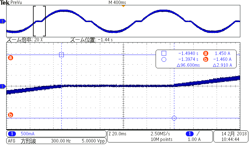
But I can never resolve distortion at zero cross.

"please see the atatteched captures."

What is the cause of in this case?
Is there any point to check?

Test conditions: VM=24V, Itorque=1.4A Micro-step=1/128

DECMOD  101 All AutoMixed decay
TBLANK    2.56us
ABT           On
TDECAY   4us
TOFF        1us

Best regards
Kei.Sugimoto

  • Hi Sugimoto-san,

    What is the sense resistor value used?
    What is the TORQUE setting?
  • Hello Rick-san.
    Thank you for replying quickly.

    >What is the sense resistor value used?

    I use it 0.05Ω same as Evaluate board BOOST-DRV8711. 

    >What is the TORQUE setting?

    TORQUE register setting is 17h 20h.
    And ISGAIN set 5 as default.
    Therefore I calculated Ifs was 1.375A.
    It was 1.41 by real measurement.

    Perhaps signal waveform is depend on characteristic of motor.
    I write relevant parameters below.

    VM :24V
    Qg :14nC   (using CSD88537ND)
    RDS :12.5mΩ (using CSD88537ND)
    RL :5.4Ω/phase
    LL :2.9mH/phase
    CL :unknown
    θ  :1.8/step
    IL :1.0A/phase
    Rsense:0.05Ω
    nm :128step

    Best regards
    Kei.Sugimoto
  • Hi Sugimoto-san,

    Many of the lower steps are within the offset voltage of the amplifier. Increasing the sense resistor should help.

    Please try adjusting your sense resistor to .3 or .33 Ohms. Reducing the blanking time to 1us may also help.