This thread has been locked.

If you have a related question, please click the "Ask a related question" button in the top right corner. The newly created question will be automatically linked to this question.

DRV8814: IC not working.

Part Number: DRV8814
Other Parts Discussed in Thread: DRV8840

[url=https://hizliresim.com/2JOQm2][img]i.hizliresim.com/.../url]

Hi,
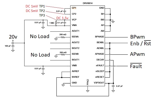
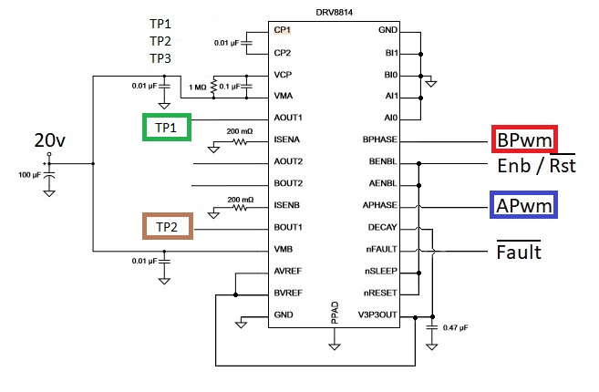
I use DRV8814 and you see my schematic. I don't want to use chopper properties of IC.
Therefore I connect Avref and Bvref pins to 3v3. A1, A0, B1, B0 pins connected to gnd.
This circuit not works.

CP1 and CP2 pin voltage nearly zero volts. VCP pin voltage around of 1.5 volts.
There are something wrong but I didn't find it. I tried different ICs but problem continue.

  • Hi Motor,

    Would you please try to re-attach the schematic?

    If VCP is 1.5V, please check VM. When nSLEEP is low, VCP should be approximately VM - 0.7V.
  • Hi,

    My schematics here.

    Charge pump not working. I changed 10nf capasitor and I tried 4 differend IC. Problem not solved.

  • Hi Motor,

    There could be a problem with the layout, or a connection problem like a solder bridge. If this is a layout problem, the devices could be damaged on power up.

    If VM = 20V, VCP should either be ~19V when nSLEEP is low or ~32V when nSLEEP is high.

    Please check your layout and then your connections after placing the device on the board. Also, if possible please power the board up slowly looking for potential problems. This should be done with a low (50mA or less) current limit on the power supply.
  • I bought 12 chips from a company that sells them cheaper than others. I encountered the problem I previously mentioned in the tests I've conducted with the first 8 chips. Now, I tested another new chip, and saw that the problem was fixed and the chip worked fine. However, in the schematic when I put in the same signal in the Apwm and Bpwm input pins, I was expecting to receive similar signals back from Aout1 and Bout1 but between the two out pins I saw that there was a 2.5 microsecond delay. 

    Since there was nothing written about delay in the pdf of the chip, I want to know if the problem occurs because of the cheap chips. Is it possible for me to find a detailed document about the signal delays and propagation for the chips. 

  • Hi Motor,

    The input to output prop delay may not be matched between the two outputs.

    As you have seen, the duty cycles appear to be maintained.

    If you are attempting to operate the device in parallel, it is recommended to use a DRV8840 instead. The DRV8840 is intended to operate in parallel.