This thread has been locked.

If you have a related question, please click the "Ask a related question" button in the top right corner. The newly created question will be automatically linked to this question.

BOOSTXL-DRV8301: Control Register 1 resets to 0, and motor stops spinning

Part Number: BOOSTXL-DRV8301
Other Parts Discussed in Thread: DRV8301, DRV8305, CONTROLSUITE,

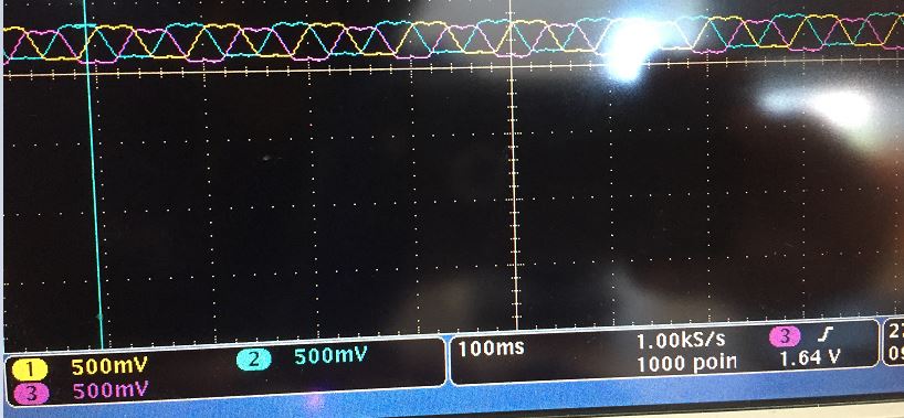
Problem: When trying to run motor control code with DRV8301 boosterpack on F28379D LaunchPad, motor initially spins, control register 1 goes to value 0 (control register 2 stays at its vlaue), then all three motor phases start outputting close to Vdc voltage. 

Goal: Please help me figure out how to fix this issue.

  • Notes:
    • I don't see any of the status led's turning on indicating a fault, and when reading the status registers, I read 0. 
    • I dont think the drv8301 booster pack resets and goes in an unresponsive state, because I am still able to read control register 2 correctly as a value of 9.
    • Please find IO assignments for 379D attached if you want to check correct assignment

  • Possible causes
    • 379D launchpad by itself
    • Don't think so
    • DRV8305 boosterpack,  which has almost the same pinout as drv8301,  works with 379D launchpad.
    • Tried a different 379D launchpad, and same issue
  • drv8301 Boosterpack by itself
    • Don't think so
    • Tried a different drv8301 Boosterpack, and same issue
    • DRV8301 boosterpack works on 377S launchpad
  • Software
    • Don’t think so
    • 8301 booster pack works with 377S launchpad
      • So as long as gpio assignments is correct, software not an issue
    • I Checked code gpio assignments
      • Works when using 8305 boosterpack with 379D launchpad, which has almost the same pinout as 8301
      • Only differences are:
        • Reordering of the Vsense pins
        • DC-Cal for 8301 is in place of Wake pin for 8305
        • Extra octw pin for 8301
        • Extra PWRGD pin on 8305
      • Thus only sources of assignment error is octw pin

F2837xS_IO_assignment.h

  • Sanmesh,

    Are you using the software that comes with the DRV8301 BoosterPack, or did you write you own? When you experience issues, is the motor connected? What is the value stored in register 0x00 when this happens?
  • 1)  am using the motor control code from "C:\ti\controlSUITE\development_kits\TIDM-SERVO-LAUNCHXS\MonoMtrServo_377s_v1_00_00_00", with modifications to allow user to switch configuration for  377S/379D launchpad and DRV8301/DRV8305 boosterpack. Main things changed were GPIO assignments for the 379D launchpad since they are different than that of 377S launchpad.

    2) I have experienced this issue with both the motor connected and disconnected. Value stored in register 0x00 of the 379D device in hex is 0040 9FCD. 

    3) When I read the registers of the DRV8301 through SPI, Value stored in both register 0x00 (status reg 1) and register 0x01 (status reg 2) of the DRV8301 is 0.

  • Sanmesh,

    If motor is not connected, and all the phases go to Vdc, my guess is that the GHx pins are all driving high, and the GLx pins are all driving low. If that is the case, then the INHx pins must be high and the INLx pins must be low. Can you check if this is the case?

    Also, can you run the software in debug mode and pause it/step through it to see if it is stuck in some subroutine that puts the motor driver in that state?
  • I measured the PWM_AH,BH,CH, pins on the boostxl-DRV8301, which are directly connected to the INH_A,B,C pins, and see the pwm waveform below when putting an oscilloscope low pass filter on the signal. The INL_A,B,C pins were ground as expected.

    However, the  GHx pins are all at almost dc level, and the GLx pins are GND.

    Thus, something tells the drv8301 to ignore the INH/L input and just send constant dc voltage on GHx pins. What could this be?

  • Also, about your question on checking whether the code is stuck in some subroutine, seeing the pwm signal go to the INx pins of the DRV8301 I think proves that the code isn't stuck in some subroutine, and I have also checked myself through running in debug mode.

    What I'd like is for you to list cases where the device would reset its configuration register or output all three GHx pins as high Vdc signals.
  • Sanmesh,

    I'm looking into that right now. Can you please let me know the voltage on all the GHx and GLx pins when the device is in the unresponsive state with the 379D board? My guess is that the GHx pins are high and the GLx pins are low, but I want to confirm.

  • Here is some info from the DRV8301 datasheet that might help debug.

    UVLO (maybe not your issue since SPI shuts down)

    A specific PVDD1 undervoltage transient brownout from 13 µs to 15 µs can cause the DRV8301 to become unresponsive to external inputs until a full power cycle. The transient condition consists of having PVDD1 greater than the PVDD_UV level and then PVDD1 dropping below the PVDD_UV level for a specific period of 13 µs to 15 µs. Transients shorter or longer than 13 to 15 µs will not affect the normal operation of the undervoltage protection. Additional bulk capacitance can be added to PVDD1 to reduce undervoltage transients.

    EN_GATE transients

    An EN_GATE reset pulse (high → low → high) from 10 to 20 µs should not be applied to the EN_GATE pin. The DRV8301 has a transition area from the quick to full reset modes that can cause the device to become unresponsive to external inputs until a full power cycle. An RC filter can be added externally to the pin if reset pulses with this period are expected to occur on the EN_GATE pin.

    Gate Driver Power-Up Sequencing Errata

    The DRV8301 gate drivers may not correctly power up if a voltage greater than 8.5 V is present on any SH_X pin when EN_GATE is brought logic high (device enabled) after PVDD1 power is applied (PVDD1 > PVDD_UV). This sequence should be avoided by ensuring the voltage levels on the SH_X pins are less than 8.5 V when the DRV8301 is enabled through EN_GATE.

  • GHx pins are 17V, with Vdc = 20V. GLx pins are 0V.

    I think the noise on the EN_Gate pin is causing the issue. I put an oscilloscope signal on the EN_GATE pin, and set the capture mode to trigger when voltage is below 2.7V. When I detect the config reg1 reset to 0, the scope triggers on the capture below, with YELLOW channel = EN_GATE, and Blue channel = INH. The voltage goes as below as 2.329V.

    There are three things to note:

    1) DRV8301 boosterpack works on 377S launchpad, but not 379D launchpad

    2) Using 379D launchpad with the DRV8305 boosterpack which has the same EN_Gate pin, works properly, and I don't see EN_GATE going below 2.9V at any time.

    3) Problem occurs when both the motor is connected and disconnected, but happens more often whe the motor is connected.

    Using these 3 facts, I think for some reason, the DRV8301 boosterpack has issues supplying enough current to the 379D launchpad, and its a board compatibility issue. Is this a correct deduction and would you recommend anything else?

  • Sanmesh,

    I'm not sure if we have enough data to make that conclusion yet. There are a couple things we would need to check to confirm that the power supply wasn't good enough. Here's a list if you want to check them.

    • If board power supply is an issue, then you should see a large dip on the 3.3-V line.
    • The timing of this ringing signal is in nanosecond range. I typically don't trust oscilloscope noise/ringing measurements in the nanoseconds range because they are usually due to probe coupling. To properly measure signals in the nanoseconds range, you need as small of a ground loop as possible for the scope probe.

    If noise on EN_GATE is truly the issue, the datasheet recommends adding a capacitor. You could put a 0.1 uF or 1 uF cap on EN_GATE. Maybe you can solder it in parallel with R6.

    One thing that your oscilloscope picture does tell us, even if the measurement comes from probe coupling, is that something in the system switches at that time. In your experiment, how did you correlate the control register 1 read of 0x00 with this EN_GATE ringing?

    If the ringing and the register change have good correlation, here are some other debug items to look at.

    • Is there anything in your code that you can correlate to this noise?
    • Does this noise occur periodically? Are there other signals on the board that you can probe to correlate this noise?
    • Is this ringing present for the 377 LP+DRV8301 BP setup or the 397D LP+DRV8305 BP setup?