This thread has been locked.

If you have a related question, please click the "Ask a related question" button in the top right corner. The newly created question will be automatically linked to this question.

DRV8303: DTC not working properly on DRV8303

Part Number: DRV8303
Other Parts Discussed in Thread: TMS320F28069M,
Good afternoon TI,
I'm using the DRV8303 along with the TMS320F28069M microcontroller on a custom BLDC motor controller board. I'm trying to adjust the PWM deadband using the DTC resistor but it is not changing with different resistances. It is also much shorter than the minimum deadband of 50ns in the datasheet. I tried replacing my original 1kOhm DTC resistor with a 22 kOhm resistor, which should lead to a dead-time of ~100ns. However, I'm still only seeing ~10ns dead-time between the high-side and low-side FETs. Do you have any suggestions as to why I'm not able to adjust the dead-time per the datasheet?
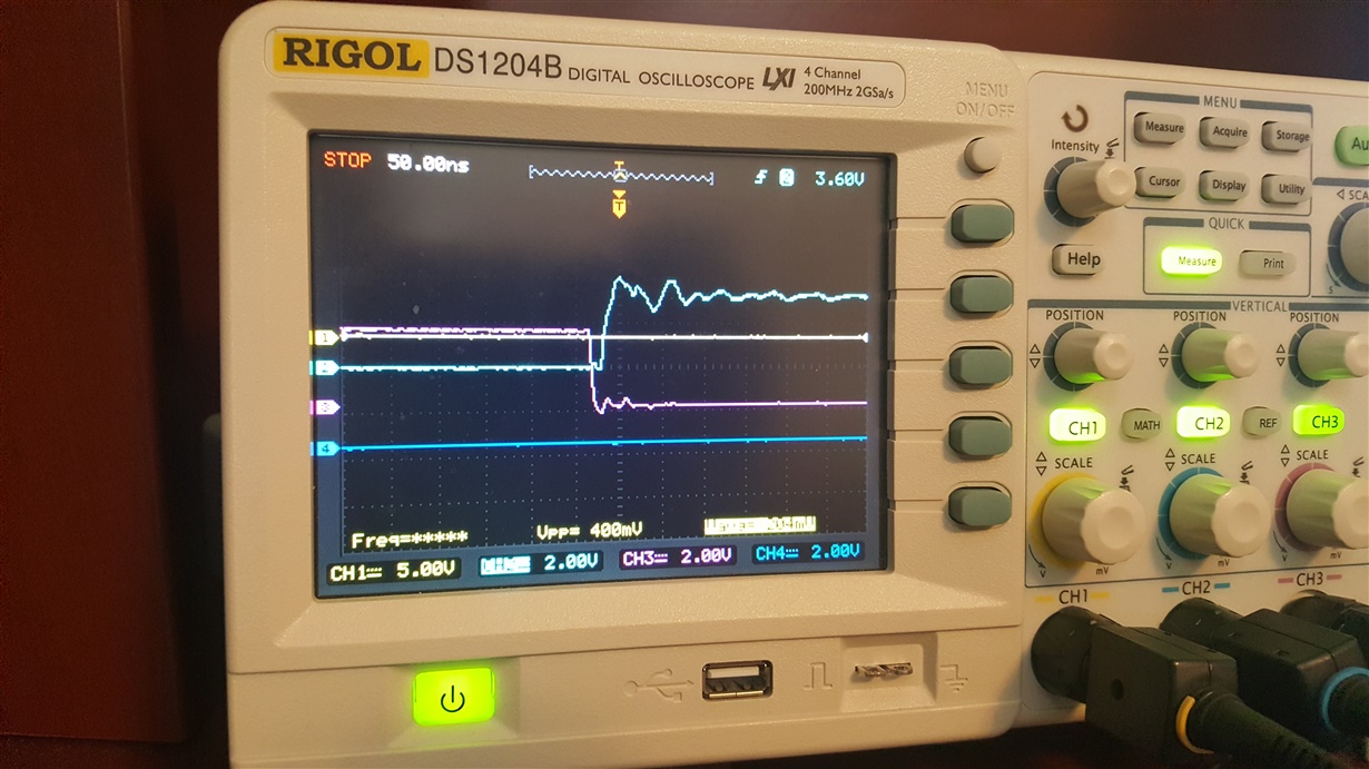
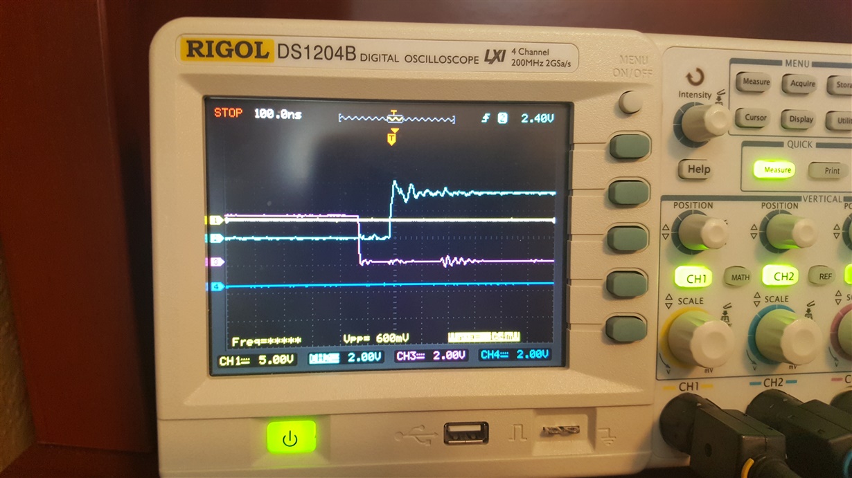
I adjusted the PWM delay in hal.h (HAL_PWM_DBFED_CNT) and found that I could adjust the deadband through these #define constants. But this still doesn't explain why the hardware DTC is not working. Here's an image of the original deadband using a 22 kOhm DTC resistor, followed by an image after adjusting the PWM delay to 20 cycles (~200ns at 90MHz).
In what cases would the DTC on the DRV8303 not function properly?
(green and red signals in image represent high-side and low-side gate signals, respectively)
Thanks,
Chris
  • Hi Chris,

    When you took these measurements, did you have FETs connected correctly to the gate-drive outputs? I'm asking because the transitions seem really fast for charging FET gates. The DRV8303 has handshaking and dead time features for controlling FET switching. If you do not have FETs connected, this may impact the timing of that circuitry.

    If you do have FETs connected, have you seen this dead time issue occur on multiple devices?
  • Good evening James,

    Thanks for the quick reply. Yes, I do have FETs connected to my system (I am using the IRFH4201 FETs). I have seen this problem on two different boards.

    Any ideas what may be causing this issue?

    Thanks,
    Chris
  • Chris,

    Do you have any components between the gate-drive output and the FET? If so, what are they? This can sometimes impact timing. Also, where are you measuring for the signals above? Sometimes the timing will look different if you measure at the gate of the FET rather than the pins of the DRV8303. This is especially true if you have extra components in this path.

    The voltage level of the signals on the oscilloscope looks incorrect for those outputs. The low-side gate output should be ~10 V when it is on. The high-side gate drive should be PVDD+10 V when it is on. Your scope shot shows that both high-side and low-side drive signals are 4 V. Is it possible the devices you are testing were damaged?
  • Good afternoon James,

    I apologize for my mistake. The signals on my breakout board were actually connected to the gate drive signals from the microcontroller (used as inputs to the DRV8303). This explains the lacking PWM deadband and also voltage levels.

    We can close out this post.

    Best regards,

    Chris