This thread has been locked.

If you have a related question, please click the "Ask a related question" button in the top right corner. The newly created question will be automatically linked to this question.

DRV8412: DRV8412 - one output not working

Part Number: DRV8412

Hi

We build for our students a demo board with 4 DRV8412. We build up 47 units but on 16 at least one driver (in most cases) one of two outputs doesn't work.

Sometimes only one is not working but they are different (not always the same output). On some of them all are not working.

We use the Dual full bridges mode (one PWM input each full bridge with complementary PWM on second half bridge) with cycle-by-cycle current limit.

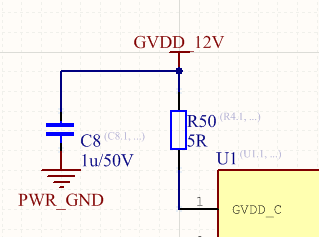
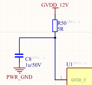
A PWM frequency between 1kHz to 10kHz. For that we select a 1uF bootstrap capacitor with one 3.3Ohm resistor.

We use the an additional inductance (100uH) at the output like on the demo board.

On some of the boards I soldered again the capacitors to make sure there is no issue with that.

One unit I could fix with that. But as I tried to solder the others to there was no success with only soldering.

I tested the outputs of one board with an external resistor to ground or VCC. And found that the upper transistor is not switching. The bootstrap voltage looks good (12V) the bootstrap diode was also working (tested with a multimeter between BST and GVDD)

What could damage the transistor in such a configuration? Do you have any advice how to find the error?

Kind regards

René

DRV8412-Bridge.pdf

  • Hi Rene,

    Your issue may be related to the size of the bootstrap caps you used. To confirm this, you may want to test with an oscilloscope rather than a multimeter to see if the bootstrap cap is actually operating correctly. The 1 uF caps might be too big. I would try 100 nF capacitors first. If those don't work, try 200 nF or 300 nF. Or, try the 100 nF caps as recommended in the datasheet, then drive with frequencies higher than 10 kHz.
  • Rene,

    I spoke to a coworker about your issue. Your 1 uF caps should be fine. The possible issue is where you placed the 3.3-Ohm resistor for the bootstrap supplies. The datasheet recommends (7.3.2.1 Bootstrap Capacitor Undervoltage Protection) placing a 5-Ohm resistor between the GVDD_x pins and the GVDD supply. However, this resistor needs to go between capacitor and the GVDD_x pin. For instance, you should put a 5-ohm resistor between C8 and GVDD_C. Do this for all all the GVDD_x supply pins.
  • Hi James

    Thanks for the answer.

    You mean the resistor should be like that:


    And NOT like that:

    The only hint in the datasheet I found was 7.3.2.1

    "When using a bootstrap cap larger than 220 nF, it is recommended to add 5-Ω resistors between 12-V GVDD power supply and GVDD_X pins to limit the inrush current on the internal bootstrap circuitry."

    One thing that could be damaged in the second picture is the bootstrap diode with the current changing the bootstrap capacitor out of C8.

    I checked that diode and it was OK (measured with a multi-meter).

    Today I changed one driver on one board (nothing else) and it's working right now.

    I think we have a problem with the soldering but I didn't understand why should this cause the problem and damage the driver.

    For the redesign I need to understand why the driver gets broken. Is it just enough to set this resistors and in case of bad soldering again it will not brake the driver?

    Kind regards and thanks for your help

    René

  • René,

    The first image is correct. The resistor needs to be added because large bootstrap capacitors have large inrush currents. When they first start charging, they act like short circuits. This large current can damage the device. Adding the resistor helps to limit the current so the device does not get damaged. The resistor needs to be placed in the circuit like you show in the first image so that it can limit the current from both the decoupling capacitor and the supply. Alternatively, you could place the resistor on the BST_x pin if you prefer.

    If the failures are due to bad soldering, I can't guarantee the device won't be damaged regardless what components you add. If you want to debug this further, you need to take scope shots of each of the voltages on the pins on working and non-working boards to identify the differences and determine root cause.