Hallo,
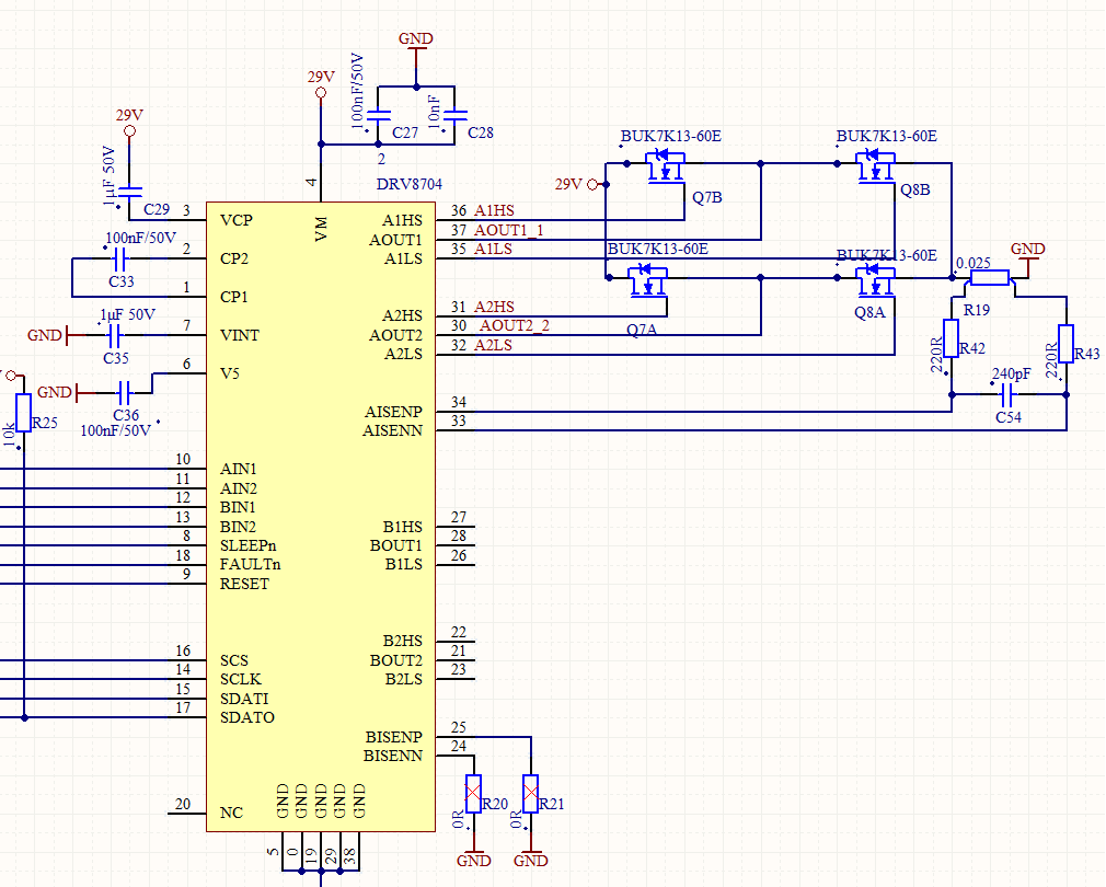
Maybe you could help me I have a problem with the DRV8704.
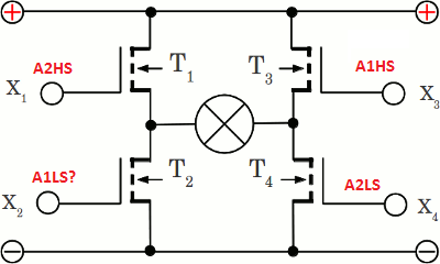
To explain the problem let’s use this numeration for the Mosfet’s:

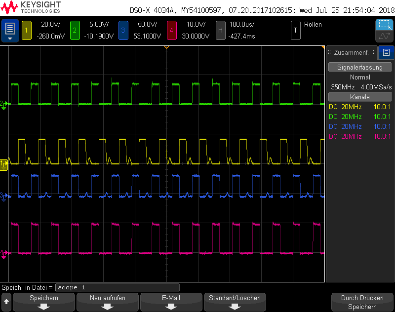
In the first Oscilloscope Picture you see on, CH 1 the signal on PIN INA1 , CH 2 the signal on PIN INA2, CH3 the signal on PIN A2HS , CH4 the signal on PIN A2LS . Let’s say PIN A2HS switch T1 and A2LS switch T4. This looks all fine in Picture the problem came now !
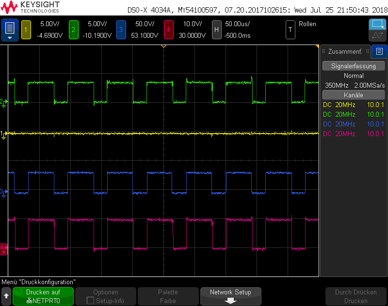
In The next Picture I measured the signal from the PIN A1HS on CH1, let’s say this is T3. All the other Channels measure the same signal like in picture one. The signal on INA1 and INA2 didn’t changed. On Pin INA2 there is still the PWM signal and the Signal on INA1 is still 0V .
I confriguated the DRV to force the slow decay mode so I wonder why does T3 turn on ?
According to the datasheet on page 12 the H-Bridge should be switch to High-Z when both input signal are Low ?
During the Measurement there was no over current event for the DRV and the second Channel were deactivated (BIN1 and BIN2 connected to GND).
Did you have any solution that T3 stay off ?.