This thread has been locked.

If you have a related question, please click the "Ask a related question" button in the top right corner. The newly created question will be automatically linked to this question.

DRV8832: DRV8832 used for Actuator

Part Number: DRV8832

Hi,

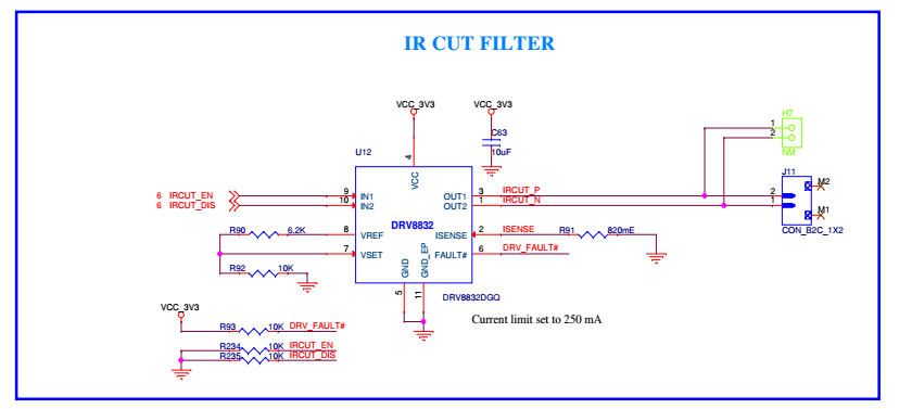
We are using the IC DRV8832 in our project. This is used to drive the IR Cut Filter in our device. This will be triggered once we check the day light condition.
But we are getting a random issue such that without giving input to the IC, IR Cut filter is getting driven. We are not able to find the root cause of the issue as this is getting randomly.  What could be the possible reason for this.
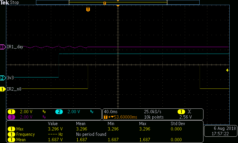
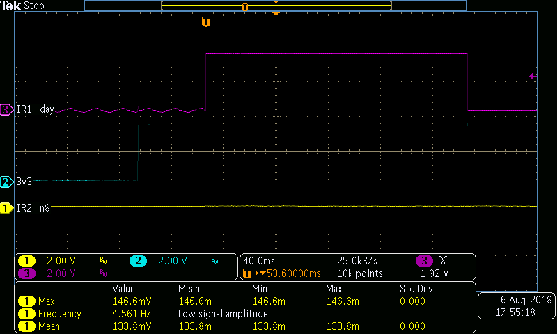
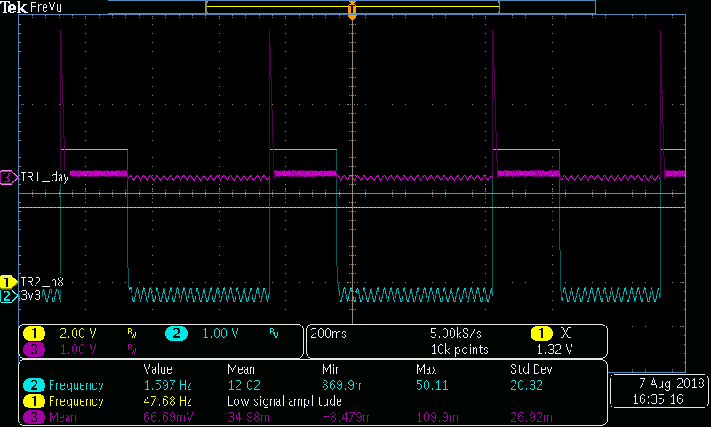
Below are the images we got once we doubt the issue was created. This was happening as soon as the supply to the IC was switch ON. Can you please check if this behavior is normal? 
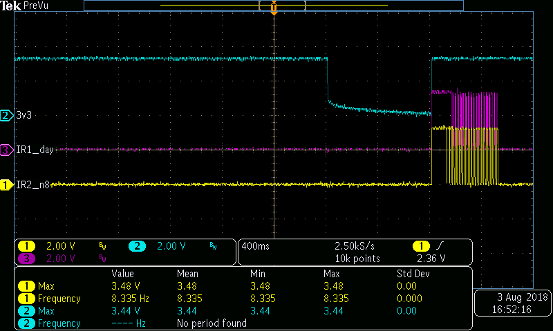
Blue- 3.3V Power
Pink- IRCUT_P
Yellow- IRCUT_N
Our IR Cut Filter trigger time is 200ms
We are using only  10 and 01 combination for driving the Cut filter. We are configuring the IN1,IN2 pins as input on the controller side during the rest of the time.

  • Hi Johny,

    What controls the VCC_3v3 signal? Is it a switch?

    Would you please zoom in and capture the IN1/IN2 signals during the 3v3 ramp up?

    During power up, it may be possible the INx signals are being coupled to VCC_3v3 and interpreted as a logic high.
  • Hi Rick,

    You are asking about the 3V3 Power supply? The 3V3 power is enabled using a PMIC. The IN1/IN2 are connected to the controller. 

    When we probe the IN pins during power up we couldn't see any voltage change.

    The issue which you mentioned during the ramp up can happen even though we have pulled low the IN1/IN2 pins? In the scheme we have pulled low the pins using a 10K resistor.

  • Hi Johny,

    Yes, I am asking about the 3V3 power supply.

    What was the time scale used and number of samples when you probed the INx signals during the power ramp?

    Please provide these signals, as it will help with our debug.

    The issue I mentioned should not happen, but it has to be checked.

  • HI Rick,

    We are not getting this issue frequently. It is happening randomly. I am sharing the waveforms during the normal operation. The Scheme which we implement can be identified using this.

    Blue- 3V3 Supply, Yellow- IN1, Pink- IN2

    Time Period- 40ms, Voltage/Div=2 V

    Fig.1---IN2 High 

    Fig.2-- IN1 High

    The Powering up and IN1/2 signal timing is done with 50ms gap. This sequencing is OK right?

  • Hi Rick,

    Did you get a chance to check the Sample Waveform. 

    Here I am attaching another waveform in which we are getting a pulse in Both OUT1 and OUT2. We are getting a ripple on the starting and ending edge of the pulse. Can you please check this and comment.

    Pink-OUT1

    Blue-OUT2

    Is there any condition that we will get a hang state in the Driver IC? 

    Once if we get the Fault Condition on the next power cycle this will revert Back?

  • Hi Johny,

    Please zoom in (20us/div or less) and provide the input pins with respect to VCC_3P3 going high. As mention, I do not expect to see any problem. We want to rule this possibility out.
  • Hi Johny,

    Since we are working off line, I will close this thread.