This thread has been locked.

If you have a related question, please click the "Ask a related question" button in the top right corner. The newly created question will be automatically linked to this question.

DRV8702-Q1EVM: test question about DRV8702-Q1EVM

Part Number: DRV8702-Q1EVM
Other Parts Discussed in Thread: DRV8702-Q1,

Hi team,

Recently I study the DRV8702-Q1 and make an experiment that use the  DRV8702-Q1EVM to drive a brush motor, then I have some questions as follows,

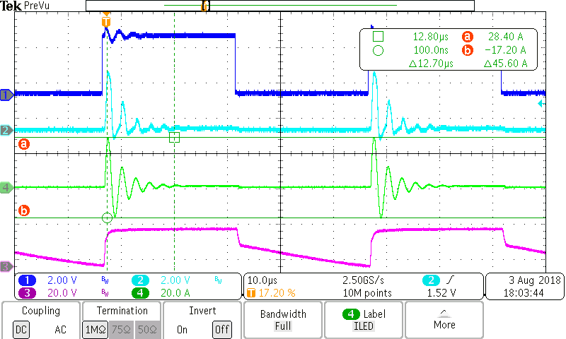
1. ch1: pin-IN1/PH,  ch2: pin-SO,  ch3: pin-GH1,  ch4: motor current

a. Why does the input(ch1) have jitter on the rising edge? In addition, experiments have found that the smaller the duty cycle of the input, the more severe the input jitter, why?

b. test condition: VREF=3.3V, Rsense=10mΩ, Av=19.8, then I calculated motor's chopping current I=VREF/(Rsense * Av)=16.67A

but in the waveform(current is green line), initial current reachs 28.4A ,Why is it so large, should it not be less than 16.7A?

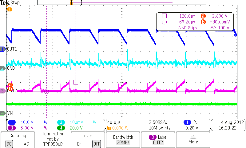
2. ch1: pin-SH1(out1), ch2: GND, ch3: pin-SH2, ch4: VM(power supply)

At this time, input's duty cycle is 70%, Why is the waveform of SH2 (purple line) gradually rising when the input PWM is 0?

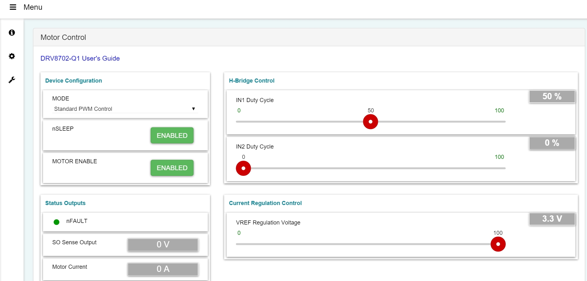
  • Could you please share a screenshot of the EVM GUI? I want to know how you have configured the EVM. My responses to your questions are below.

    1a) Are you referring to the ringing on ch1? I believe the ringing on ch1 is coupling from the source of the ringing that you observe on ch4. Jitter is a different phenomenon

    1b) This waveform is strange to me for a few reasons:

    • The timing of the GH1 signal matches the IN1/PH signal, so this makes me think that the device is not actually chopping the current.
    • The GH1 signal looks strange when IN1/PH is low. It seems to be discharging slowly. I expect it to discharge quickly and have a sharp edge.
    • When I look at the current on ch 4, I see large ringing, but overall, the current level is 0-A. This is very strange if you are expecting 16-A. It almost seems like something is damaged or nor connected correctly.

    2) If current flows through the motor from OUT1 to OUT2, I expect the OUT1 voltage to dip and the OUT2 voltage to increase. As for why this happens when PWM is 0, it depends on how you configured MODE. Which MODE setting are you using? How are you driving the INx pins? (the screenshot of the GUI should help to explain this)

  • This is the screenshot of the GUI.

  • Hi Sherry,

    Is item 2 still an open issue for you? I apologize for my delay. I had to take time to support other requests.