This thread has been locked.

If you have a related question, please click the "Ask a related question" button in the top right corner. The newly created question will be automatically linked to this question.

DRV8848: Partial Parallel Mode

Part Number: DRV8848

Hello,

I'm designing with the DRV8848 motor driver and I have a unique hookup that I wanted to run by you all before I commit to a prototype. I'm driving two motors, but only one will ever need to be on at any given time. Normally I would use both full bridges in the driver to control each motor individually. But other constraints in the design requires me to reduce the amount of control lines in a cable as much as possible.

Both motors will have one of their terminals connected together for a common line. Then the other two lines will be connected to the other pins individually. This allows full polarity control on both motors, but only one at a time. 

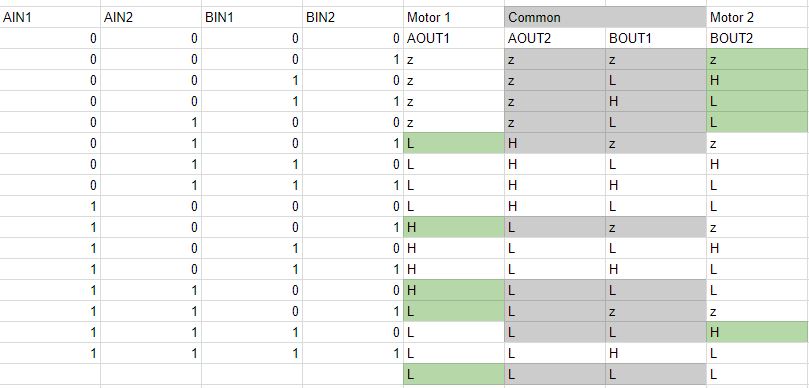
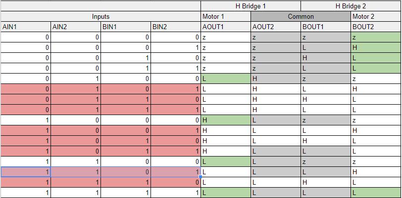
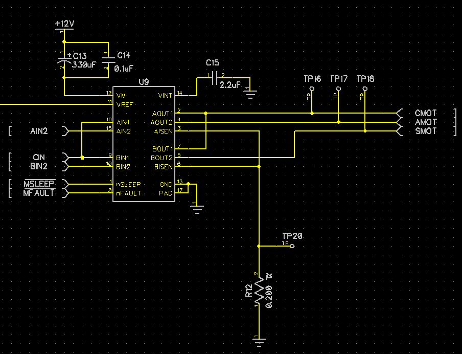
So I want to control both motors with only 3 lines. Since there are 4 half bridges in the driver, I am going to put two of them in parallel and use that output for the common connection, and the other 2, one for each motor.

See the picture for a schematic. 

In the datasheet, it says to float AIN1 and AIN2 in parallel mode. I'm assuming this is to prevent parallel bridges from shorting out by driven them opposite of each other. But it mentions that they must be floating on power up or coming out of sleep. So I didn't know if there is some special logic in there that puts it into parallel mode or something on startup.

I'm assuming that there are 4 input pins and AIN1 controls half bridge, AIN2 control half bridge 2, BIN1 controls half bridge 3 and BIN2 controls half bridge 4. And those go directly through the logic to the gate drivers. In order for my setup to work I need to use the AIN lines as well as the BIN lines, So the AIN lines will not be floating on startup.

Will parallel mode still work in this case?

  • Hi Matt,

    Do you intend to set AIN1/BIN1 to high? If so, it appears you will create a condition where you must operate both motors or create a short between AOUT1 and BOUT1.

    Do you need to connect AOUT1 and BOUT1 together? If not, this may work, since you can set the unused motor in brake mode.

    The DRV8848EVM is available to evaluate your options.

    What you are trying to do is not the parallel mode described in the datasheet. Parallel mode as described in the datasheet uses two of the four input pins to synchronize the outputs and provide more current to a single load.
  • You're right. I had to go through the truth tables to find out a way. Not sure I like it though. 

    Below is all the input states. Then AOUT2 and BOUT1 are connected together to provide the common motor line. All gray highlighted states are states that do not short out the AOUT2-BOUT1 connection. The green highlighted states are the states that can be used to apply all 4 polarity options on either motor, while the other motor is off or braked. 

    Firmware will have to be very careful not to apply the other input states to not short the driver outputs.

  • Hi Matt,

    Current regulation should also be considered. If the DRV8848 enters current regulation, the ouputs are reversed as fast decay is entered. This can cause the common outputs to be in opposite states.

    States AIN1/AIN2/BIN1/BIN2 equal 1,1,0,1 and 1,0,1,1 are of concern. The others should be OK.
  • Thanks for catching that. Here is it updated. I fixed the alignment of the inputs and output too.

    All input states that are not red can be used without fear of shorting. All red input states should never be used. Would you agree?


  • Hi Matt,

    Yes, I agree. As previously mentioned, the DRV8848EVM is available for evaluation prior to building your board.
  • I just thought of another scenario. I do have the DRV8848EVM on order to test.

    I still have the two SENSE pins connected to each other using one sense resistor.

    So for input of "0100", if the bridge that is on starts to regulate and switch polarity, what happens to the other bridge driven to High Z? Is it forced to the same polarity as the other bridge? This would turn on the other motor.

    I have AOUT2 and BOUT1 connected, I can't have two separate current sense resistors, if AOUT2 and BOUT2 are driven low, the current will be pulled from both ground paths and the sense resistors will be in parallel and the current regulation won't work properly anymore. Currently, if one bridge regulates they both will think it's time to regulate.

  • Hi Matt,

    The other bridge should remain in the high-Z state with input of "0100".

    The DRV8848EVM is set up so you can connect the two sense resistors together using a jumper. It was not intended for this purpose, but should work.