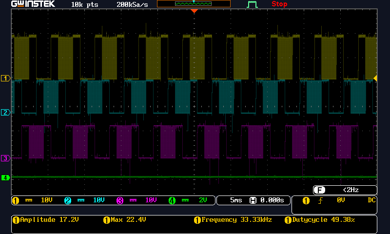
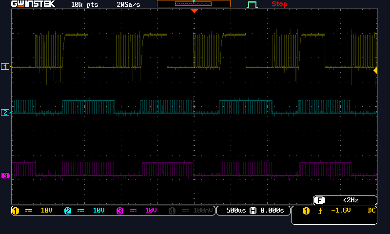
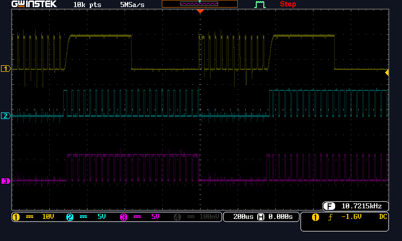
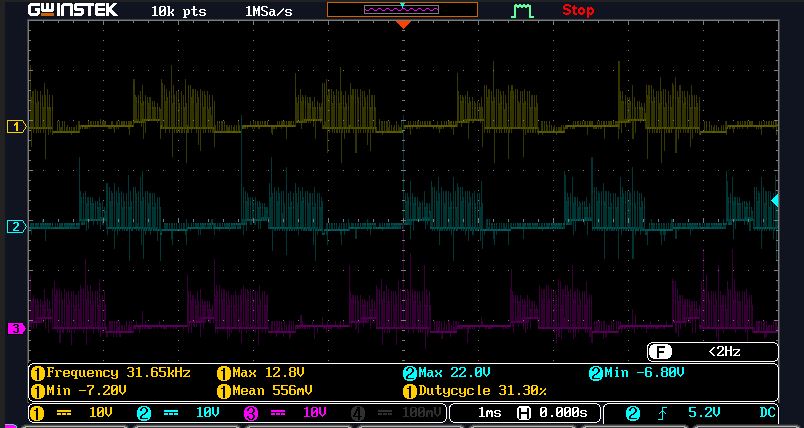
I am using DRV8305 MOSFET driving IC. I am not getting PWM output from this.
This thread has been locked.
If you have a related question, please click the "Ask a related question" button in the top right corner. The newly created question will be automatically linked to this question.
Hi Rashi,
Can you provide some information about your system setup?
Thanks,
Garrett
Hi Rashi,
Are you testing with the motor connected, or are you directly observing the outputs of the IC? If your motor is hooked up, please disconnect it for now to make debugging easier.
Can you measure your inputs on the INLA/INHB/INLB pins? If all three of those inputs are low, then as per the State Table for 1-PWM mode, all of the gate outputs will be held low.
Thanks,
Garrett
Hi Garrett
Thank you for your kind reply
Yes we are testing it with the motor disconnected and checking for waveform on GHx and GLx as well as INLA/INHB/INLB also, on MOSFETs output.
There is 1Khz PWM signal on INHA and switching sequence being applied to INLA/INHB/INLB as per figure-8 in the datasheet and a continuous low on INHC.
period for each signal is about 2ms and each signal overlaps the previous signal by 1ms.
The nFault pin remains low, after reading the SPI status registers the PVDD undervoltage flag remains high even though when we are applying 12V on PVDD.
Thanks
Rashi
Hi Garrett,
There is an update to previous message
We have detected Fault Bit Register in Address 0x1 is High, AVDD undervoltage flag (AVDD_UVLO, bit D5) in register 0x3 and PVDD undervoltage flag (PVDD_UVLO2, bit D10) in register 0x3 is also high. Although we have given 12V on PVDD, the voltage on VReg pin is at 2.89V only. From the data sheet, shouldn't we get 3.3V output from Vreg pin in case of DRV83053? Or do we have to supply 3.3/5V from external source?
Thanks
Rashi
Hi Rashi,
Let's address these faults individually:
1) PVDD_UVLO2
PVDD_UVLO2 is triggered by PVDD falling below 4.4V. Usually I see this fault occur when either the power supply does not supply sufficient current, or the PVDD supply on the board is otherwise constrained. What is the current limit on your power supply? How much capacitance do you have connected to PVDD? Are there any other components restricting the connection of PVDD to the power supply?
2) AVDD_UVLO
AVDD_UVLO is triggered by AVDD falling below 3.7V. This is potentially related to the PVDD dropout, since AVDD is supplied from PVDD. It could also be related to the AVDD regulator itself. How much external capacitance is attached to the AVDD pin? Are there any other external components attached?
3) Vreg Voltage
If you are using the DRV83053, then yes, the VREG pin should be regulating the output closer to 3.3V. How much external load are you placing on VREG? How much external capacitance is connected to the VREG pin?
Thanks,
Garrett
Hi Garrett,
1) we have attached the oscilloscope pins on PVDD input supply voltage and there is no sign of voltage drop recorded on the oscilloscope. That means it is steady 12V supply.
we have connected 4.7uF capacitor from PVDD to ground. Any other component is not restricting the power supply.
2) only 1uF capacitor attached to AVDD, no other components.
3) 1uF capacitor attached to Vreg.
my concerns are:
1) nfault pin remains low from start.
2) can we test the circuit without the H-bridge, just to make debugging easy?
Hi Rashi,
All of those components are the datasheet-recommended values, so they seem fine.
1) If nFAULT remains low from the start, the PVDD_UVLO may just be from PVDD rising slower than the device start-up sequence. Before attempting to apply the PWM input, could you write a "1" to the CLR_FLTS bit in register 0x9 to clear the device faults? Then see if any new faults occur when the PWM input starts.
2) Yes, however, this may cause VDS faults, since the gate won't turn on to connect the drain and source
Thanks,
Garrett
Hi Garrett
Thank you for your support.
My problem has been resolved .
I have connected SN1, SN2, SN3 pin for back sensing, which makes AVDD pin to ground .
Please help me with 6-mode input signal, waveform below shows the output in 1-mode and 6-mode
MOSFET output in 1-mode
output in 6-mode
channel-1 is MOSFET output from phase-A, channel-2 is input to AH and channel-3 is input to AL.
I want to know how to give input in 6-mode.
Thanks
Rashi
Hi Garrett, First of all, thank you for patience and kind responses. We have so far made the Motor Spin. But there have been issues which i will try to describe below: The circuit is made as per application circuit from the Datasheet of DRV8305. We are driving it in Single PWM mode with PWM Signal of frequency 31.25KHz @15% Duty Cycle
being applied to INHA, where as a MCU applies a state sequence (AB 0110, CB 0100, CA 1100, BA 1000, BC 1010, AC 0010) at Pins INLA, INHB and INLB (INHC is fixed low for
the time being). The controller ramps up the sequence timing from 450RPM to 4000RPM. The whole system is operating in open loop configuration, as our aim is to drive the Motor in sensorless mode. Therefore initially it applies commutation sequences without any
feedback. Once the Open Loop System is stable, we would then proceed to integrate the sensorless feedback system. We are using a 12V 3A DC Supply. The supply current is limited to 3A for testing purposes. The Motor is kept at No load condition. 1) The result is that the Motor Spins upto 2100RPM and suddenly stalls and all the Gate Drivers are disabled. Although if the Duty Cycle of PWM signal is kept at 50%, the motor doesn't start on its own, but if we spin the motor externally during the initial period, and so if the motor catches
up with the sequences, the motor spins and accelerates upto ~3976 RPM and stays stable. Is this issue related to Power? or are the PWM duty cycle & ramping sequence not in sync, and if so what would be the relation between PWM duty cycle and commutation timing? 2) The second issue is that during power up there are sparks seen between pins 37 to 48, and due to some reason the IC heatsup and this results in a short between DVDD and GND pin.
here output waveform, i.e at pins(SH_A, SH_B and SH_C), attached below
When load is not connected
When load is connected
Thanks
Rashi
Hi Garrett,
1) yes, fault register 3, bit D4 i.e VCP_LSD_UVLO2 fault is detected. I there any way to disable this?
2) Happened on multiple units so we replace peripherals with the new one which resolves the sparks problem. Voltage rating of capacitor on pins VCPH, CP1H/CP1L, and CP2H/CP2L are 25V, 50V and 50V respectively.
Thanks
Rashi