This thread has been locked.

If you have a related question, please click the "Ask a related question" button in the top right corner. The newly created question will be automatically linked to this question.

DRV8702-Q1: stall current fault

Part Number: DRV8702-Q1

Hi team,

I'm writing you to ask  two questions about DRV8702-Q1.

Question 1:  Stall current detection failed

The customer use Standard PWM Control Interface mode, during toff period, the current drops. The required stall current is 20A, the customer doesn't use internal current detection of DRV8702. They use ADC integrated in the MCU to sample current, and when the current ups to 20A, the MCU control the motor stop. The ADC's sampling rate is 4k, which is much smaller than PWM's frequency(20k).

The problem is that when the stall occurs, sometimes it can't detect the stall current.

Could you please help give a solution about the question?

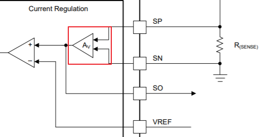
In addition, if I add a RC filter on the output of the amplifier(shown as below), how should I set the value of R and C so that it can't affect the performance of the amplifier. Could you tell me the input resistor and feedback resistor of the amplifier?

Question 2:  nFault pin

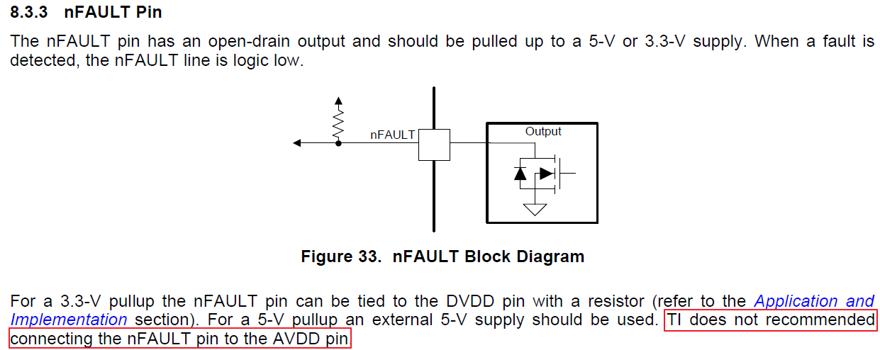
Why is the nFault pin not recommended to connect to AVCC? Could you please help explain it?

Thank you very much!

Sherry

  • Sherry,

    1. I want to clarify few thing about your first questions:
    "The problem is that when the stall occurs, sometimes it (MCU) can't detect the stall current."
    What does the stall current look like? DC or AC current?
    For debugging purpose, can they verify the MCU with a DC current? Can the MCU detect it? How big the difference is between DC current and Stall current?
    "RC filter on the output of the amplifier"
    a. First, if they want to use the RC filter to filter out the noise or spike on the current sense circuit, they have to know what does the signal look like? I want the RC filter time constant to be few times higher than the noise pulse width.
    b. Also, the R cannot be too high, it is related the MCU ADC input impedance. If the ADC input impedance is much lower than current amplifier's output resistance (including the RC filter's series R value), they may not detect the true current.

    2. I would think the DVDD and AVDD timing difference is the reason of why "TI doesn't recommend connecting the nFault pin to the AVDD pin." Check the page 24:
    During the device power-up sequence, the DVDD pin is enabled first. Then the MODE pin latches. Finally the
    AVDD pin is enabled. For setting PWM control interface, TI does not recommended connecting the MODE pin to the AVDD pin. Instead the MODE pin should be connected to an external 5-V or 3.3-V supply or to the DVDD pin if not driven by an external microcontroller (MCU).