This thread has been locked.

If you have a related question, please click the "Ask a related question" button in the top right corner. The newly created question will be automatically linked to this question.

DRV10987: Using DRV 10987 Evaluation Board but No control over Motor Speed via Analog/PWM input at speed pin

Part Number: DRV10987
Other Parts Discussed in Thread: USB2ANY

Hi,

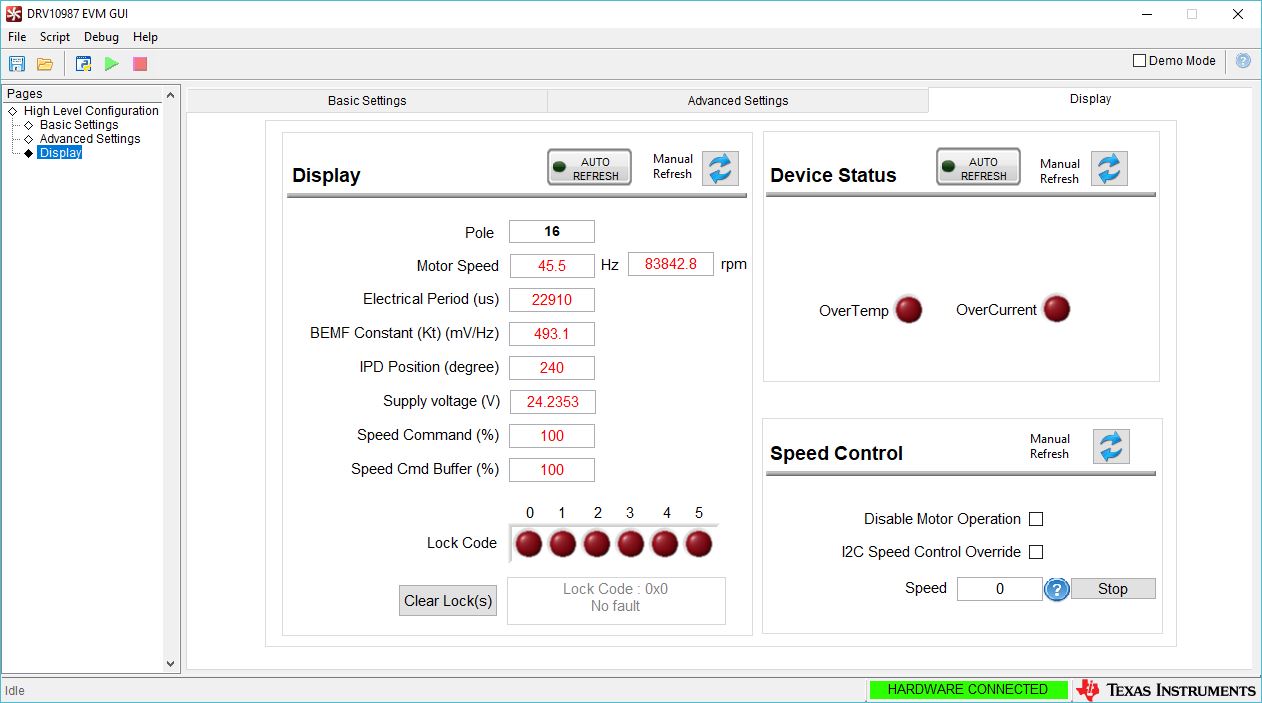
I am using DRV10987 EVM. I am trying Tuning the BLDC Fan Motor. 

The Motor Parameters are:

Rph = 1.26 ohm /ph

Lph = 6.75 mH/ph

Kt = 400 mV/Hz

The Configuration file I have is attached below.

I have 2 issues:

1) First of all, although I am able to run the motor, the motor runs at full speed (for any input value) or zero speed (for 0 input) through the USB2ANY I2C via DRV GUI, but no speed control by either GUI or PWM or Analog Methods resp.

2)  Secondly, the motor start up takes time, it turns ON and OFF couple of times and then ultimately turns ON completely and runs at full speed after 40 seconds. I am using Initial Speed Detect and Initial Position Detect. So some start up delay is expected but is it possible to minimize the same.

Please suggest suitable measures to have a minimum starting time and smooth speed control 

Thanks,

PratikTI_com_param.cfg


  • Hello Pratik,

    Let me answer your questions below:

    1. First of all, although I am able to run the motor, the motor runs at full speed (for any input value) or zero speed (for 0 input) through the USB2ANYI2C via DRV GUI, but no speed control by either GUI or PWM or Analog Methods resp.
      1. This is a problem when the Kt value is unoptimized and Mechanical AVS is enabled. Please see this post and read the first reply that explains the issue in a bit more detail

    2. Secondly, the motor start up takes time, it turns ON and OFF couple of times and then ultimately turns ON completely and runs at full speed after 40 seconds. I am using Initial Speed Detect and Initial Position Detect. So some start up delay is expected but is it possible to minimize the same.
      1. If I understand you correctly, the motor attempts to start up a couple of times until it successfully ramps up to the full speed? This sounds like the motor driver is triggering some lock or fault that will prevent the motor from starting up. Going to the display tab in the GUI and observing the locks 0-5 might deliver more insight to what is going on
      2. Usually, unreliable start up behavior is a result of incorrectly programmed motor parameters. Read the reply to the question "How do I get the motor running" in this post. Note, incorrectly programmed motor parameters also relate the issue above.

    I'd also like to say, that the brake time is a bit high. Remember, brake time is the time of delay between measuring the motor phase <24mA (after a stop command is provided) and the align phase of the motor. Decreasing it, should decrease your start upt ime.

    Best,

    -Cole

  • Hey Cole,

    Thank you so much for your sincere reply. It helped a lot !

    However, I am still concerned about certain issues:

    1) I have calculated Kt (= 400 mV/Hz) as per Tuning Guide, however, as I look into the GUI Display Tab, the calculated BEMF constant Kt displayed is 306.4 mV/Hz and also the speed in rpm displayed is several times higher than the motor speed in rpm

    2) The motor start-up time has reduced ( owing to disabled current limit for lock detection ) as it was going through multiple On-OFF cycles. Still it displays Lock Code 0 .

    Also further as I enter into the closed loop operation, it immediately shows, Lock code 1 and 2 are also activated.

    So, my questions are:

    a) Whether it is feasible to disable the Lock Code 0 detection  (i.e on Current Limit) or there is any other way out ?

    b)  If the calculated Kt is apt, then why Lock Code 1 and 2 are activated in the closed loop operation.

    c)  The rated speed of BLDC Fan Motor is 375 rpm. With EVM and GUI, the maximum speed I could achieve was only 330 rpm. How do I achieve rated speed ?

    Please kindly suggest suitable remarks for the same.

    Thank You.

    Regards,

    Pratik

  • Hey Pratik,

    I'm glad it helped a bit. Let me address your new questions:

    1.  Also the speed in rpm displayed is several times higher than the motor speed in rpm
      1. Unfortunately, this is a known issue with this version of the GUI, we plan to release a newer version to fix the calculation. If you do the calculation by hand you should be able to look at the electrical frequency box and use the equation to calculate it
        RPM = 120*f_electrical/n_poles
    2. Whether it is feasible to disable the Lock Code 0 detection  (i.e on Current Limit) or there is any other way out ?
      1. It is feasible to disable the Current Limit (Lock 0) and rely on Over Current Protection (4A Typ.) for current protection. Usually, this is used when customer would like to push higher power in our devices.
      2. With that said, whenever a protection is disabled, the user should always check if the remaining locks will catch any specific unwanted behavior (such as a locked rotor condition)
    3. The rated speed of BLDC Fan Motor is 375 rpm. With EVM and GUI, the maximum speed I could achieve was only 330 rpm. How do I achieve rated speed ?   If the calculated Kt is apt, then why Lock Code 1 and 2 are activated in the closed loop operation.
      1. Just to be clear, we are talking about those locks appearing after spending some time in closed loop, not necessarily right when the device tries to enter closed loop, right? Lock 1 and 2 are both related to the programmed Kt again, I'd like to just confirm that the Kt_calc (shown on the GUI) closely matches the Kt_prog (the value in manually placed in the box on basic settings tab) leading up to the Lock 1 and Lock 2 activation.
      2. If both Kt's match, then we need to make sure Tcontrol is tuned the RPM right before the triggers occur. If they do not, then manually match the Kt_prog to the Kt_calc.

    If this keeps happening then we'll need to gather some waveforms and see what the phase current and voltage is doing.

    Best,

    -Cole

  • Hey Cole,

    I have tried tuning as per your post.

    I hereby list down my observations:

    1) During both  Open loop and Closed Loop operation, the actual speed measured and the speed calculated using formula

    (speed = 120*f_electrical/n_poles) does not match.

    2) Supply Voltage read from GUI is less than the actual supply voltage.

    3) Max. motor speed is still 330 rpm.(below rated speed even at max speed input)

    Also, I am still facing issues as  mentioned in earlier post related to  programming Kt value.

    I attempted it as per  your suggestions in previous posts but still it seems to be not optimal (programmed Kt and Kt viewed in GUI  are unequal) I hereby attach the configuration file.

    Kindly do suggest suitable means to optimize Kt value.

    Thanks,

    PratikTI_com_param2.cfg

  • Hey Pratik,

    1.  During both  Open loop and Closed Loop operation, the actual speed measured and the speed calculated using formula (speed = 120*f_electrical/n_poles) does not match.
      1. I should have been given a little bit more context. We expect up to a 7% mismatch been the actual motor speed and the electrical frequency box in the GUI. If the period box is used, the mismatch goes down below 1% (RPM = 120/(n_poles*T_electrical*10^-6)). Alternatively, measuring FG frequency with an oscilloscope should yield the most accurate value for the speed of the motor (because FG is the actual commutation frequency).
      2. Because of delays in GUI calculation, I trust measuring FG and plotting it over time the most, and then the GUI in closed loop only
    2. Supply Voltage read from GUI is less than the actual supply voltage.
      1. That is very strange, we've only seen that one other time. Essentially, the device on the EVM was pre-production silicon and some internal registers were not correctly set which lead to strange Kt and a lower supply voltage (like you may be seeing)
      2. As a result make sure the top markings on the IC do not have "P" somewhere to indicate "prototype" silicon (e.g. DRV10987P)
    3. I attempted it as per  your suggestions in previous posts but still it seems to be not optimal (programmed Kt and Kt viewed in GUI  are unequal) I hereby attach the configuration file. Kindly do suggest suitable means to optimize Kt value.
      1. You've mentioned the way to try and tune it. If the programmed and measured value are different, keep "chasing" the measured value by changing the Kt value until they are the same

    1. Also, I attached some very conservative settings you should continue testing with. It has your Kt, Rm, and Lead Time. We want to make sure other settings are not causing the problem.

    TI_com_param3.cfg 

    Best,

    -Cole

  • Cole,

    Your previous post helped a lot ! Thanks. The Motor works fine.  In reply to the previous post I would like to add:

    1) I am able to read correct speed via FG pin.

    2) The DRV10987 does not indicate "prototype silicon". I simply followed your suggestion : " If the programmed and measured value are different, keep "chasing" the measured value by changing the Kt value until they are the same ". Now the voltage displayed is as per attached file GUI Screenshot.

    Now my only concern is that the motor speed control is limited as follows:

    Lower Limit  27.6 Hz  i.e 207 RPM for any GUI Speed Command  below 280

    Upper Limit 45.2  Hz  i.e 335 RPM for GUI Speed Command 511

    My question is :

    How do I control motor for lower speeds or at higher speeds because rated motor speed is 375 RPM ?

    Thanks,

    Pratik

  • Hey Pratik,

    Let me split these into two separate problems:

    1. Lower Limit  27.6 Hz  i.e 207 RPM for any GUI Speed Command  below 280.
      1. 280/511 means that we have an input speed command of about 54%. I see no reason why we cannot put a speed command <280 and have the motor follow. Does the driver trigger a lock and stop spinning if the speed command input is <280? If so, what Lock is shown using the display tab and looking at the code?
    2. Upper Limit 45.2  Hz  i.e 335 RPM for GUI Speed Command 511
      1. This is the max speed command, 511/511 = 100%. If I understood you correctly, 375RPM is the max rated RPM of this motor, correct? Right now, we are sitting at 90% of the max speed rated for this motor. Unfortunately, there is not a whole lot that can be done. The only way to increase the speed is manually increase our motor parameters and hope we don't trigger any locks.
      2. This means, we need to incrementally increase the value in the Kt box, and change the Abnormal Kt Lock Detect Threshold to Kt_high = 2Kt, Kt_low = 1/2Kt on the Advanced Settings tab in the Lock Detect section. We may have to disable some locks to get the motor to spin faster
      3. I will note that we currently moving outside of the typical use cases for algorithm and I cannot guarantee this will work.

    Best,

    -Cole