This thread has been locked.

If you have a related question, please click the "Ask a related question" button in the top right corner. The newly created question will be automatically linked to this question.

DRV8312: Running at low frequency, prevent booster from reloading

Part Number: DRV8312

Hi All

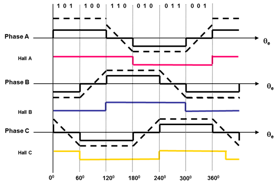
I try to use DRV8312 on a 3phase synchronous motor in a strict "block-commutation" mode. That means, that each of the lines only switches twice per rotation. 

Our motor runs at rotations speeds from 10000/min to 60000/min, that is from 166Hz to 1KHz. So the time a high side transistor needs to stay on without switching can last up to 2ms. 

As the high side FETs are NFETs, their gate voltage is generated with the booster-capacitor / diode mechanism. The DRV8312 is quite smart, it can detect, that its booster voltage to drive the high side fets is no longer sufficient, and decides on its own, that an additional switching cycle is necessary to reload the booster capacitor. 

The DRV8312 is designed to run with a setup in PWM mode, so the lines are frequently switched by a PWM pulse to lower the actual output voltage

In this situation, the lines are frequently switched, that there is always sufficient booster voltage available. 

In our design, we don't want PWM, neither do we want the DRV8312 to decide on it's own to switch a phase to reload the booster capacitor. So we experimented with enlarging the booster capacitor. This works to a certain amount of capacity, but it was never sufficient, to have no in-between-cycle switching. 

Is there a possibility to supply DRV8312 from an external Voltage to feed its high side driving stages? In our design, we are running the motor at 12V. So the high side is never higher than 12V. We 24V available. Is there a way to feed it to the DRV8312, so it does not need to use the booster capacitors? 
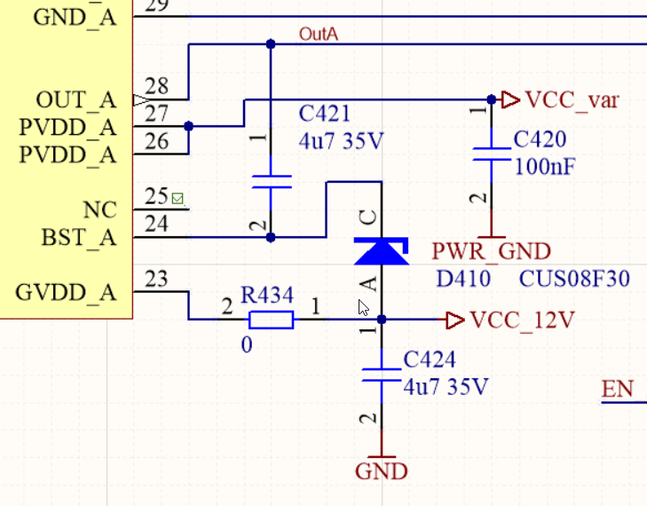
Like this?

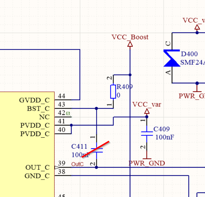
Remove C411 and feed booster directly through R409 from 24V?  Obviously we missed something, we tried and DRV8312 didn't like this. I vigorously tried to create additional switching pulses. 

Is there a way to have DRV8312 not decide to switch one line on it's own? 

Thank you for your help

Johannes

  • Hi Johannes,

    Because you are still switching the outputs, please consider increasing the C411 capacitor to 4.7uF.

    See section 8.3.2.1 of the datasheet. You can limit the inrush current placing a 5 ohm resistor between the local GVDD_x capacitor and the GVDD_x pin. Another approach is to bypass the path completely and add an external schottky diode from GVDD to the BST_x pin. This should eliminate any inrush current issues.
  • Hello Rick
    thank you for your advice. What do you mean with "Bypass the path" exactly? Remove C411 and have a schottky Diode from G_VDD to BST_x?
    GVDD is fixed 12V, PVDD can variy from 0 up to 24V. I still don't understand, how a schottky-diode from GVDD to BST_x can help? How can the supply voltage of the high side driver be higher than PVDD in this case? Does this only work, when GVDD is higher than PVDD?

    Thanks again
    Johannes
  • Hi Johannes,

    Sorry I was not clear. You will still need C411. The external schottky from GVDD to BST_x effectively bypasses the internal diode path and charges the bootstrap cap instead of using the internal diode path.

    You will also still need the GVDD_x connections.

    Please note the diode path in the functional block diagram. An external schottky can be sized to handle the inrush current of the larger capacitor.
  • Hello Rick

    Thanks for your advice.

    I patched my board like this:

    this is helpful. The unwanted recharge-pulses are gone. 

    But... Now there is a startup issue. The DRV8312 is not willing to start up properly. The output is completely strange. Obviosly the boosters don't start properly when I first apply power at a very low frequency. The Output is completely wrong and has nothing to do with the applied PWM  / Reset Signals. 

    When I apply a high frequency, the device eventually gets on it's feet, Once the device is running, I can lower the frequency down to 66Hz without the DRV8312 generating additional pulses. 

    Can you suggest something, to help DRV8312 to start properly? Shall I change R434 to 4R7? Is the new schottky-diode mounted correctly? You mentioned "from GVDD to BST". In this case: Where to put the resistor? Like shown in the schematics? Or connect the Diode directly to Pin 23.

    Thanks again

    Johannes

  • Hi Johannes,

    At startup, are you pre-charging the capacitors by setting all outputs low?

    If not, please try setting the outputs low then start.

    The schottky diodes can be mounted as shown or the anode can be placed at the GVDD_x pins (pin 23 as shown). The goal is to provide the 12V to the bootstrap capacitor using the schottky diode instead of the internal diode path.

    If you are using the schottky diode, there is no need for the resistor R434 because the schottky carries the current.
  • Hello Rick

    thank you for your advice. 

    Yes you are right, we are not starting from all lines ZERO, but from all lines Tristate. I changed that. This helped "kind of". This procedure works:

    • PVDD = 0V
    • Have all PWM Inputs = LOW
    • Have all Tristate Inputs = High
    • We can apply a variable voltage. We apply 5V on PVDD
    • Switch to a block commutation scheme with minimum of 140Hz rotation speed
    • Unfortunately our motor cannot start at 140Hz. But the DRV8312 now runs properly.
    • We lower the frequency to 70Hz (once DRV8312 runs, this is possible, now our motor starts) 
    • Now we can choose every frequency and supply voltage we want. The DRV8312 is running properly.

    Can you think of anything else to help the DRV8312 to start from PVDD=0V and this large booster capacitors?

    Thank you for your help. 

    Johannes

  • Hi Johannes,

    From your description, the DRV8312 is now operating properly. Is that correct?

    If so, this appears to be a problem with the motor startup procedure.

    What does the motor do when attempting to start at 140Hz?
    Does it move at all?

    Is it possible to start at 70Hz (or some other frequency) for a short time (<500ms) and then switch to 140Hz?

  • Hello Rick

    No, sorry that's not the case. This image shows my 3 Motor lines. in case of DRV8312 not starting properly. Obviously ony one line tries to drive a the motor, but obviously there is a problem with the booster voltage. The DRV8312 generates These burst of switching pulses to generate a driving voltage for the high side FETs. This signal is visible on the other lines as well through the connected motor. Obviouly the other drive lines of the DRV8312 are still in tristate. 

    In this Situation, of course, my motor does not start.

    Once the DRV8312 has started properly, it generates a proper drive line pattern

    Now my Motor starts without any Problems.

    So the DRV8312 has difficulties with the enlarged 4,7microFarad Booster capacitor. 

    I found out today that, even when DRV8312 runs properly, and I lower the frequency below 100Hz, it falls back into this "bad mode" shown in the first oscilloscope Image.

    Enlarging the Booster caps helps eliminating the unwanted additinal Switch pulses, but adds instability to the system. 

    Any advice, how I can stabilize the system? 

    Thank you 

    Johannes

  • Hello Rick

    I found out yesterday, that the instability is also caused by an interaction between DRV8312 and my variable voltage Regulator feeding PVDD.

    For now, thank you for your help. Before I can investigate any further, I Need do a redesign of my board and choose a new voltage Regulator. I will add your requested components as a placement option. 

    Thanks for you help

    Johannes