This thread has been locked.

If you have a related question, please click the "Ask a related question" button in the top right corner. The newly created question will be automatically linked to this question.

DRV11873: Driver is not responding for PWM for 68ms

Part Number: DRV11873
Other Parts Discussed in Thread: LMP8646

Hi,

We have designed current control circuitry for BLDC motor. We are using ' DRV11873 ' in it.Our circuitry senses current (We are using 'lmp8646' current sensor for sensing phase current) from three phases of BLDC motor then rectified output of current sensor is given to the ' BUCK ' controller (TL2575HV - ADJ) and PWM output of buck controller is given to the driver.

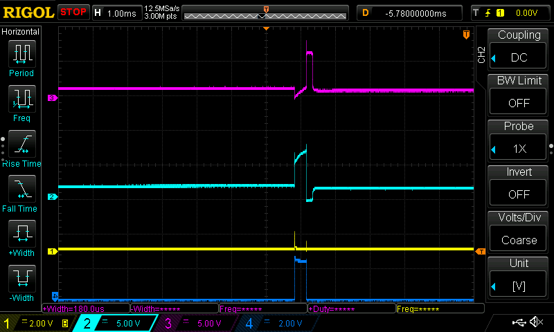
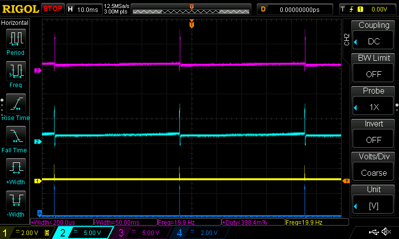
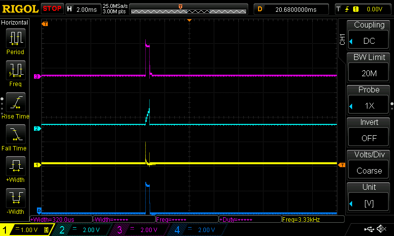
Issue Facing in testing :- Driver is not switching for nearly 68ms even if PWM input given to it . which can be seen from inserted scope wave forms.

Blue - PWM input to DRV11873 (50kHz frequency, 98% duty cycle)

Violet - rectified output from current sensor(proportional to the phase current of BLDC  

  • Onkar,

    I assume you are saying that to the left of the pulse on the violet trace has PWM input applied for 68ms before you see the current measurement on the violet trace.

    Are you monitoring all 3 phase currents or only a single phase current? When initial PWM is applied 2 phases are energized (one high one ground) and the 3rd is floating. The device looks for a zero crossing on the floating phase before switching driving states. Depending on the inertia of the motor and the BEMF constant I could easily imagine that it takes over 68ms before getting a zero crossing. If you aren't monitoring all 3 phases then you might not see the current and thus a delay before your controller comes back to shut of the PWM.

    Could you plot the phase currents and phase voltages?

    Thanks,
    Brian
  • Hello Brian

    Thanks for the reply.We are monitoring the current in 3-Phases in both the direction and the wave forms that i have sent is the rectified version of all the phase current.So we must get current proportional output also in startup condition.Also the wave form I have sent is periodic .

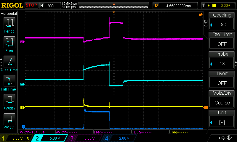
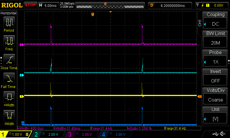
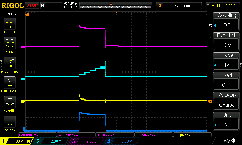
    Here is brief explanation of this issue: After the controller started to giving PWM. Current pulse is getting nearly at its feedback pin nearly after 50-60 mS .As this pulse is larger than reference of buck controller gives low then driver stop switching so current becomes zero but after that controller resumes switching but driver is not responding for previously mentioned time and this cycle continues.I attached the  wave forms of three phase voltages and rectified current output

    1,2,3 are the phase voltages and last one is rectified current waveform

  • 1,2,3 are the Phase current wave forms at each current sensor output.and 4th one is rectified current output
  • Onkar,

    Thanks for the extra pictures.

    How does the current sensor fit into your system? Are you placing a shunt in series with each of the phases and using 3 current sensors?

    Thanks,
    Brian
  • Hi Brian

    We are using 6 current sensor in our circuit. Three for sensing current in one direction and remaining three for sensing current in reverse direction. outputs of these sensors brought to one node and given to the FB pin of buck controller and PWM output of controller is given to the driver.

                                   As current sensor have precision half wave rectifier at its output so we can joint their output and this satisfies our purpose of rectification.We are using buck in system as it has error amplifier so  it will give pwm output to eliminate  phase current error 

    Motor Control circuit block diagram.pdf