This thread has been locked.

If you have a related question, please click the "Ask a related question" button in the top right corner. The newly created question will be automatically linked to this question.

DRV8840: DRV8840 motor drive IC OCP conditions

Part Number: DRV8840

Hello

When I using DRV8840, regarding OCP function, I could fully understand how OCP function operated like 6A/3.75us

but I have a question related to abnormal condition  that current level over 6A but time duration is less than 3.75us.

For example, in case of 8A peak current applied under 1us time dulation, Is it possible to operate OCP function ?

When the time duration is much less than 3.75us, what is maximun current level level for the OCP

and how can I figure out this condition? 


  • Hi Lee,

    "For example, in case of 8A peak current applied under 1us time dulation, Is it possible to operate OCP function ?"

    A peak current of 8A for 1us should not cause the OCP function to activate.

    "When the time duration is much less than 3.75us, what is maximun current level level for the OCP
    and how can I figure out this condition? "

    The OCP should not activate in less than 3.75us. There is an internal circuit that limits the current through the FET during an overcurrent condition (like a short circuit or inrush current to charge a capacitor).

    The OCP function is designed to allow current peaks above the OCP limit. Once the current is detected to be above the OCP limit, effectively a timer is started to check the current is still above the OCP limit at the end of the timer. If the current is still above the limit, the OCP function is activated.
  • Hi Rick,

    Thank you for your quick response.

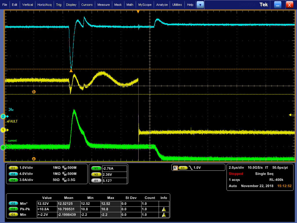
    Could you check below picture ?

    In the figure below, the current over 6A flowed 370ns, and it seems that OCP function activated because the nFalt was driven low.

    According to your explanation, OCP should not activate under the following conditions.

    In this case, is OCP malfunctioning? Could I suspect that this issue caused by DRV8840?

  • Hi Lee,

    Can you provide some additional information?

    Where is the current in Channel 4 and Channel R1 measured?
    Can you provide a scope capture of the ISEN voltage during the same time?
    Do you have a capacitor across the ISEN resistor? Adding a 0.1uF capacitor has helped in some cases.
  •   Hi Rick

      We measured current which is for the motor load

    and absolutly we have 100nF ceramic capacitor across the ISEN registor

    and this is the picture that you wnat

    And this is enlarged picture to measure overcurrent timing

  • Hi Lee,

    Would you please confirm the following pin pairs are connected together?

    5 and 10
    6 and 9
    7 and 8
    12 and 13

    If the connections are broken the device could overcurrent at lower currents.

    Also would you please confirm the method to remove the fault?
    Is the motor disabled until nRESET is applied, VM is removed and re-applied or nSLEEP is applied?
    If the motor is re-enable, this is not an overcurrent event.
  • Hi Rick

    Always thanks for the quick response

    We have checked about pin pairs as your guide but there is no issue about it

    and could you rephrase below sentence cause I couldn't understand what meaning it is

    "Is the motor disabled until nRESET is applied, VM is removed and re-applied or nSLEEP is applied?
    If the motor is re-enable, this is not an overcurrent event."

    To remove fault condition we removed VM and re-applied as the guide of specification sheet

    Overcurrent Protection (OCP)
    An analog current limit circuit on each FET limits the current through the FET by removing the gate drive. If this
    analog current limit persists for longer than the OCP time, all FETs in the H-bridge will be disabled and the
    nFAULT pin will be driven low. The device will remain disabled until either nRESET pin is applied, or VM is
    removed and re-applied.

  • Hi Lee,

    Sorry I was not clear regarding the question I asked. You were clear on the response.

    An Overcurrent event requires either nRESET or VM to be cycled to re-enable the outputs. Cycling nSLEEP will also re-enable the outputs, and is being added to the datasheet in a future edit.

    Since the outputs remained disabled until you removed and re-applied VM, this is an overcurrent event.

    I don't see what is causing the overcurrent.

    We have ruled out the obvious causes. Please allow me to ask a few more questions.
    1) What is the nSLEEP connected to? If it is a pullup resistor, what value is the pullup and what is the voltage measured at nSLEEP?
    2) Do you have this overcurrent issue on one board or many? If so, how many show the issue and how many work?
    3) What is timing between nSLEEP, VM, and nRESET when the device is powered up?
    4) Can you provide a schematic and layout? If necessary, we can make arrangements to share the schematic and layout privately.
  • Hi Rick,

    1) What is the nSLEEP connected to? If it is a pullup resistor, what value is the pullup and what is the voltage measured at nSLEEP?

        -> There is a 10kohm pullup resistor and when problem re-produced, we have not noticed any issue


    2) Do you have this overcurrent issue on one board or many? If so, how many show the issue and how many work?

       -> We have 4 PCA have same problem and we could notice that nFault signal driven to low about 1time per 100 try


    3) What is timing between nSLEEP, VM, and nRESET when the device is powered up?

      -> In our system, reset signal tied up with high level, so there is no control about it

          and we have checked other signal during the operation but we have not noticed any problem regarding nSleep signal, nEnable


    4) Can you provide a schematic and layout? If necessary, we can make arrangements to share the schematic and layout privately.

      -> I think there are no issue in schemetic design, cause we have been used same schemetic design for a long time

     And we have a question about another nFault signal condition which is UVLO

    By the specification sheet, when the VM is under 8.4V, it could be nFault function operated, Is it right ?

    When the nFault signal driven to low, we have noticed VM voltage drop to 12.5V

     so this situation could make some problem?

  • Hi Rick,

    I'm waiting for your response.

    Would you answer the question above?

  • Hi Lee,

    Sorry for the delay.

    And we have a question about another nFault signal condition which is UVLO

    By the specification sheet, when the VM is under 8.4V, it could be nFault function operated, Is it right ?

    The UVLO nFAULT function can operate below 8.2V.(typically 7.8V). A UVLO fault recovers as the voltage increases above 8.2V.

    When the nFault signal driven to low, we have noticed VM voltage drop to 12.5V

    so this situation could make some problem?


    VM dropping to 12.5V is a possible sign of not enough bulk capacitance at the VM pin.

    Do you have a 0.1uF at each VM pin to GND?

    What is the voltage on the nSLEEP pin when the device is awake? The external pullup and internal pulldown create a voltage divider.

    Another experiment to try is lowering the nSLEEP pullup resistor to 1kOhm. Please try this and report if there is improvement.

  • Hi Rick,

    Do you have a 0.1uF at each VM pin to GND?

    -> VM dropping to 12.5v can be a problem. But if the 12.5V is not UVLO, I think nFalt isn't relation with VM voltage drop. We will complement VM drop situation.

    What is the voltage on the nSLEEP pin when the device is awake? The external pullup and internal pulldown create a voltage divider.

    Another experiment to try is lowering the nSLEEP pullup resistor to 1kOhm. Please try this and report if there is improvement.

    -> The volatage on the nSLEEP pin when the device is awake is below. We had already provided you with this picture.

    The current external pullup  is 10kohm, and we tested the nSLEEP pullup resisotr with 1kOhm but there is no improvement.

    Thank you always.

  • Hello Rick,

    Can you comment on my below reply?
  • Hi Lee,

    Sorry of the delay, and thank you for reminding me about the nSLEEP voltage in the image.

    I have not observed this behavior previously.

    We have seen that false overcurrent events may appear if:

    1) there is high current and no 0.1uF capacitor across the sense resistor
    2) negative pulses of ~400ns and less than 2.2V appear on the nSLEEP signal

    You said that you have used the same design schematic design for a long time.

    Has anything recently changed such as:
    Board layout
    Board vendor
    Capacitors vendors
    Other?

    Would you please provide the markings on the top of the device?
  • Hi Rick,

    Sorry for bothering you.

    I eager to find the cause of this problem.

    There are no changing.( Board layout, board vendor,capacitors vendors, others.)

    And, I have a question about your opinion.


    1) there is high current and no 0.1uF capacitor across the sense resistor
    2) negative pulses of ~400ns and less than 2.2V appear on the nSLEEP signal

    According to the specification, the logic level is as follows.
    What is meaning of "less than 2.2v appear on the nSLEEP signal" ?
    If the nSLEEP signal under the range 0.7v~2.2v can cause the overcurrent event ?
    Thank you always.

  • Hi Lee,

    If nSLEEP is below 2.2V and above 0.7V, the state of the pin is unknown (could be interpreted as a input high or input low).

    If interpreted as an input low, there is a chance the device could begin to enter sleep mode and then see the signal as an input high. A short negative pulse in this region could cause a false overcurrent. We have not observed this behavior in the DRV8840, but it could be a possibility.

    That is why I requested changing the pullup on the nSLEEP pin to 1k. Lowering the pullup resistor should have helped with noise immunity. 

    Also, would you please provide the markings on the top of the 4 devices that show this behavior? Do working devices also have the same markings?