This thread has been locked.

If you have a related question, please click the "Ask a related question" button in the top right corner. The newly created question will be automatically linked to this question.

UC2625: UC2625 Average Current Sensing

Part Number: UC2625

Hello,

I'm looking to implement average current sensing with the UC2625 because using the pulse-by-pulse sensing seems to be limiting the needed in-rush current to my motor.

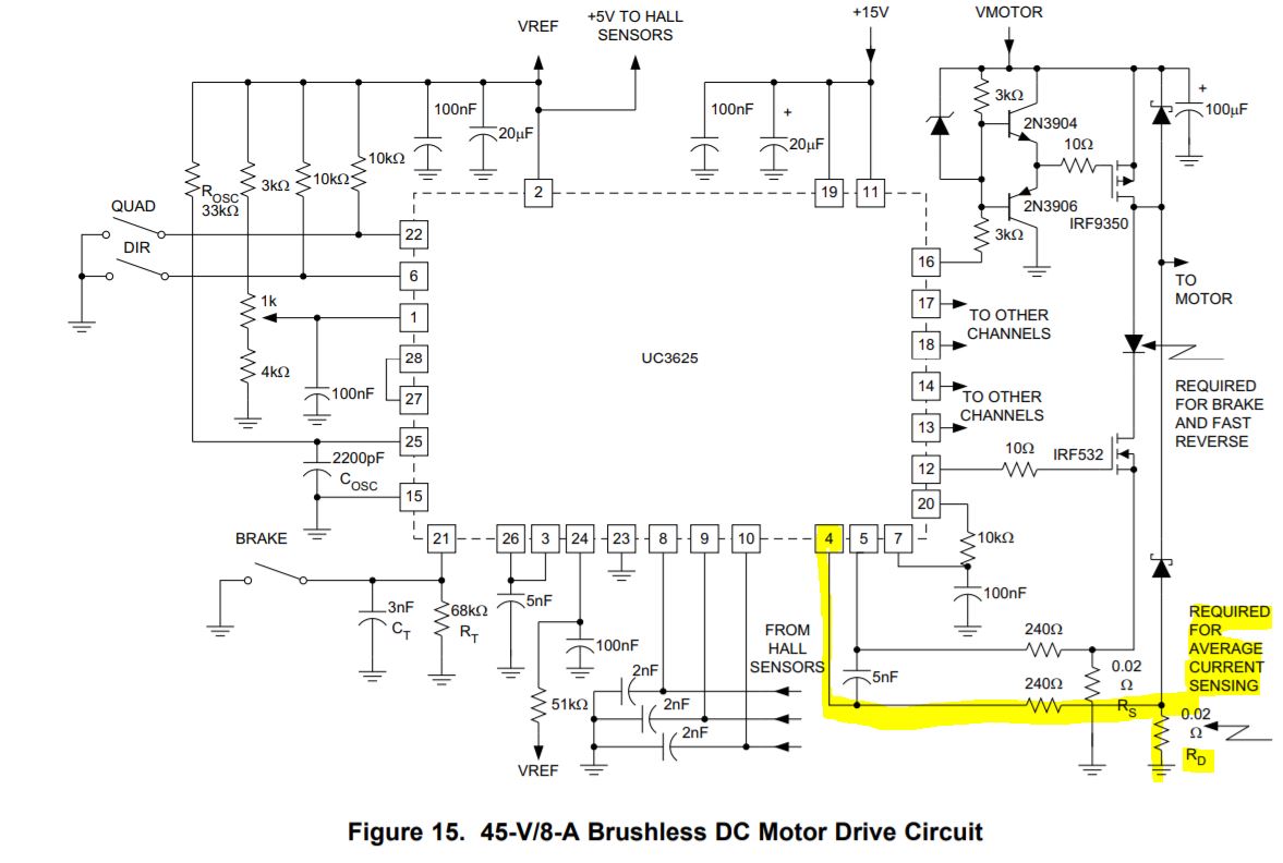
I see that Figure 8 in the datasheet states Figure D (shown below) can achieve average current sensing with the addition of the diodes and R_D. In my schematic below I've added the 6 low-side circulating diodes and extra current sense resistor. The rest of the circuitry minus this addition has been tested and verified without these extra components.

I have two questions:

- Is this a correct implementation of what the datasheet is referring to? I'm having trouble seeing how this will allow average current sensing.

- will this now allow the motor to receive the in-rush current that it needs?

Thanks in advance for the support!

  • Hello HP77,

    An expert has been notified of your question and should respond accordingly.

    Best,
    -Cole
  • Thanks, Cole. Any update?

  • Hello HP77,

    Let me answer your questions below:

    - Is this a correct implementation of what the datasheet is referring to? I'm having trouble seeing how this will allow average current sensing.

    Almost correct. As shown by the by the picture above, the expectation is that  the result from this current sense resistor goes to one of the Isense pins. Since Isense1 and Isense2 are differential inputs, the differential between the discontinous current in Rs and clamping current done through Rd results will result in average current. 

    I do understand why the figure is misleading with an arrow coming off the top side of Rs and another arrow off the bottom of Rs (GND). 

    - will this now allow the motor to receive the in-rush current that it needs?

    If the current in your system is particularly choppy then an overcurrent condition is less likely to be triggered by checking average current. This would increase overall current into the system.

    That being said, more inrush current can come from a few sources. Decreasing gate resistors to the FETs will increases the inrush current to a FET to turn it on faster. FETs with lower RDS will deliver more current as well.

    Unfortunately, both are complicated to model with equations so I suggest you leave footprints on your board and experiment with different values.  

    Best,

    -Cole

  • Cole,

    Thank you for your response! I haven't had a chance to test this out yet but I've fixed it on my schematic and it makes much more sense now.