This thread has been locked.

If you have a related question, please click the "Ask a related question" button in the top right corner. The newly created question will be automatically linked to this question.

DRV8871: Motor Stalls at 100% PWM Duty Cycle

Part Number: DRV8871

Hello,

I'm a product developer and electrical engineer working with the DRV8871 in an existing circuit.

We're having a bug. Here's the background:

  • The motor can successfully lift 15 pounds if a 100% duty cycle is used on IN1
  • The motor stalls when trying to lift 20 pounds if a 100% duty cycle is used on IN1
  • The motor can successfully lift 20 pounds if a 99% duty cycle is used on IN1

Fixes I have tried:

  • We had the Current Limit resistor set to 34K, to limit to 2 Amps and received this issue. The value was then dropped to 27k, to allow for 2.3 Amps, which did not help. Then I dropped the value to 15k to disable current limiting, and this did not help either.
  • I have shorted IN1 to ground, as the control method, and we get the same results. So this is not an issue with the control line inputs.
  • I have also increased the bulk capacitance on the Vmotor line from 10uF and 0.1uF to 47uF and 0.1uF. Still I am receiving the same results.
  • One time, randomly, everything worked fine and the motor could lift 20 pounds using 100% duty cycle input, but I have no idea why and haven't been able to replicate this.
  • I also have a large fan blowing straight on the DRV8871 chip, so I dont believe temperature is the issue

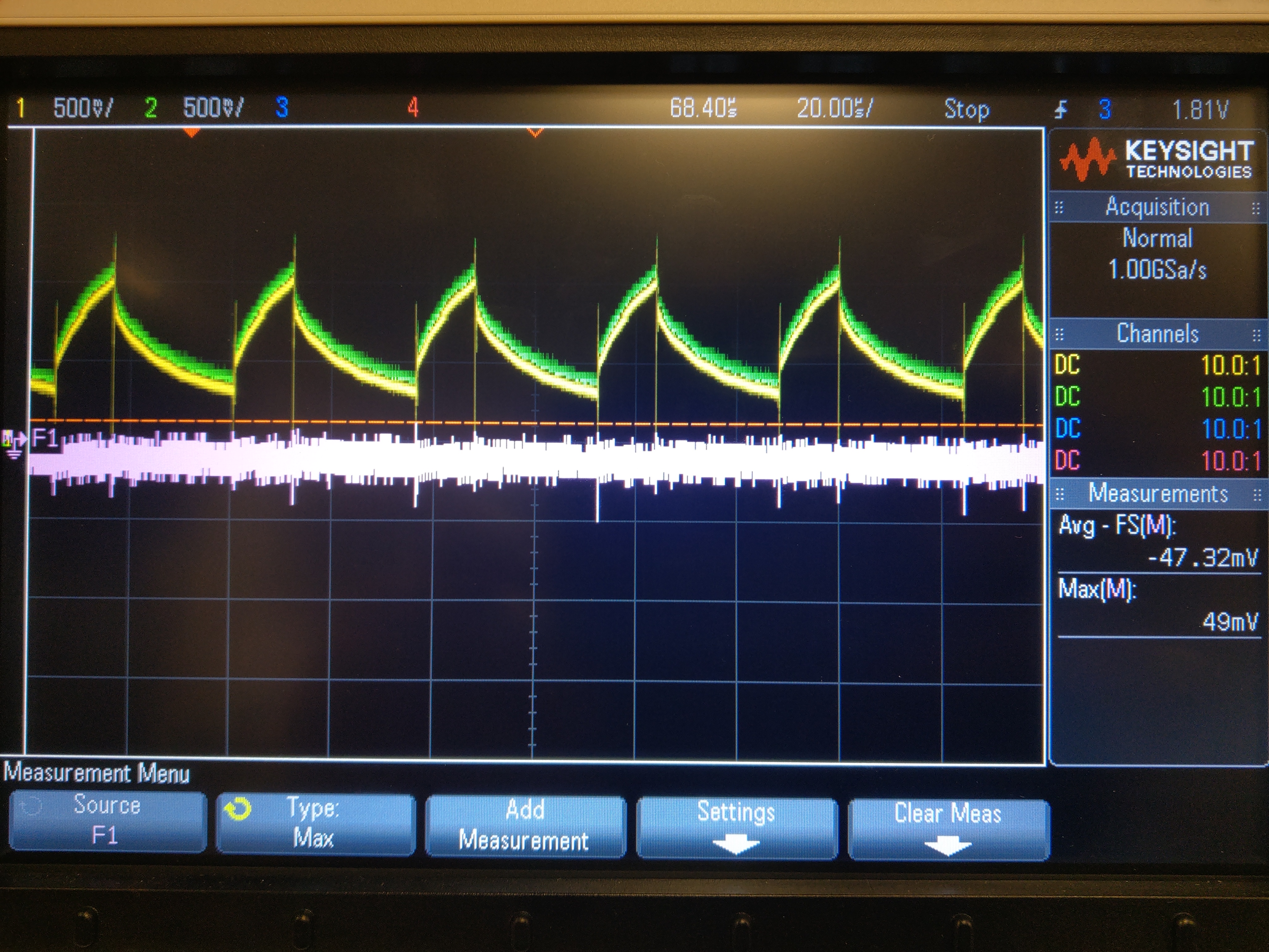
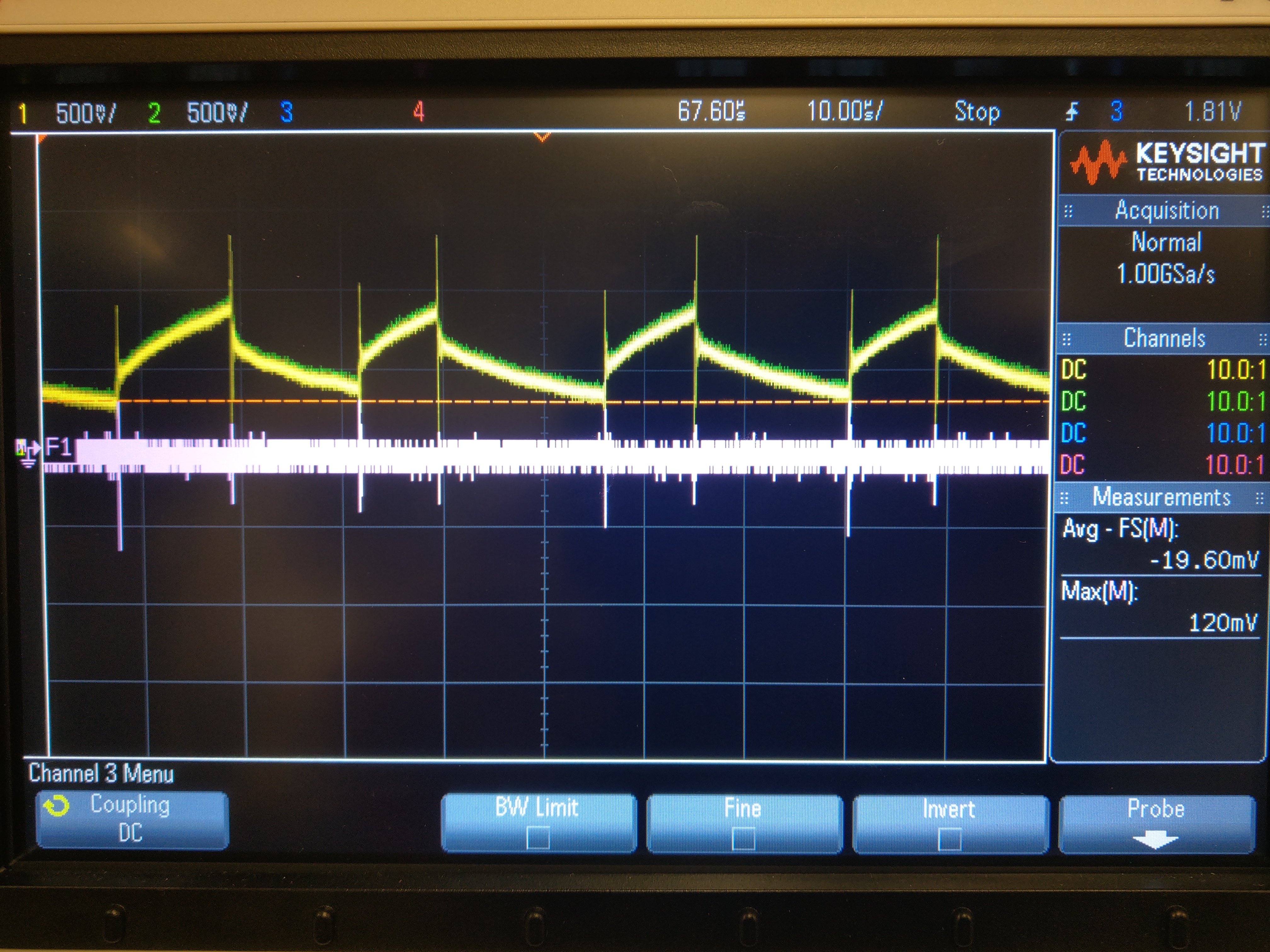
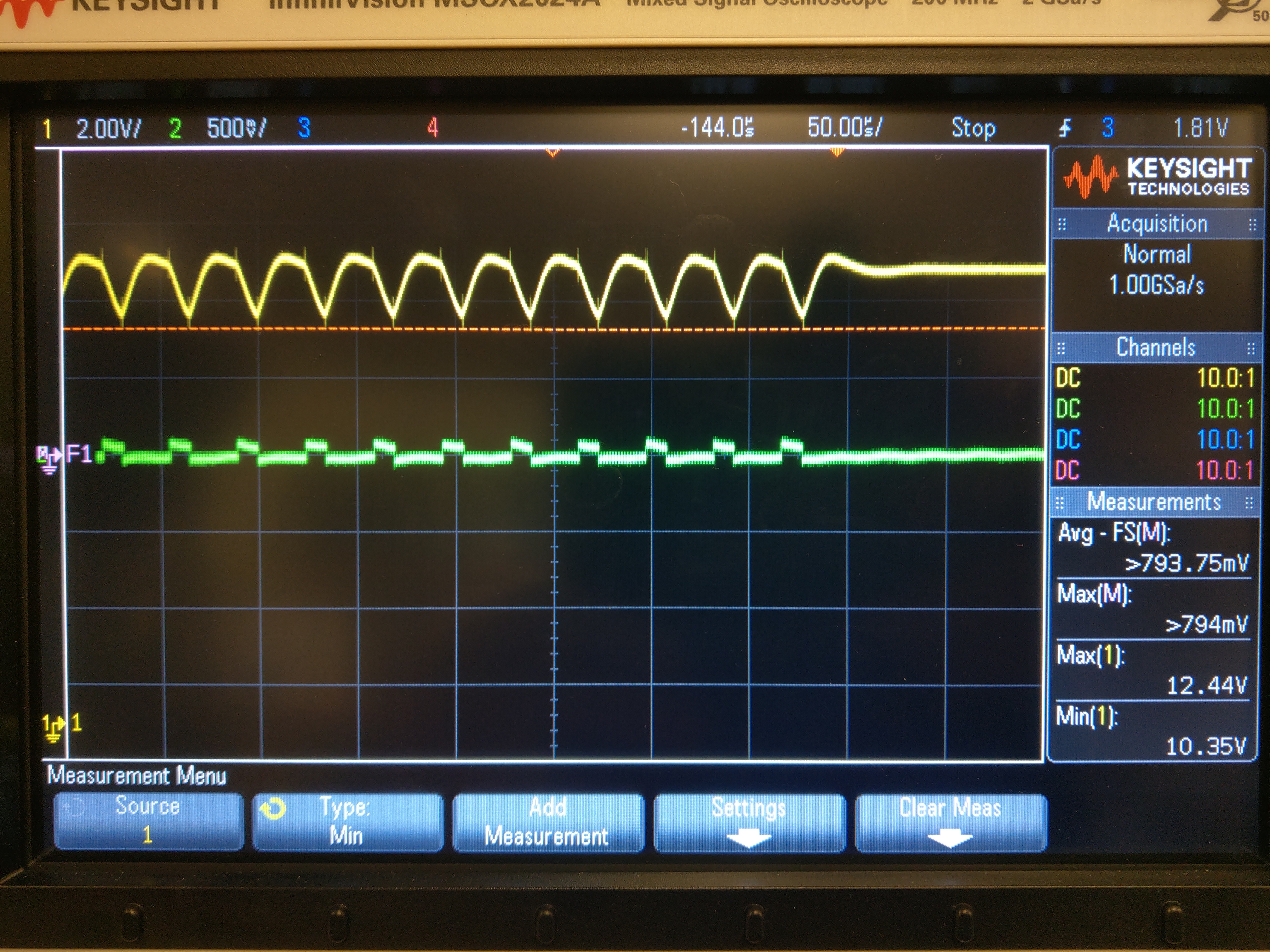
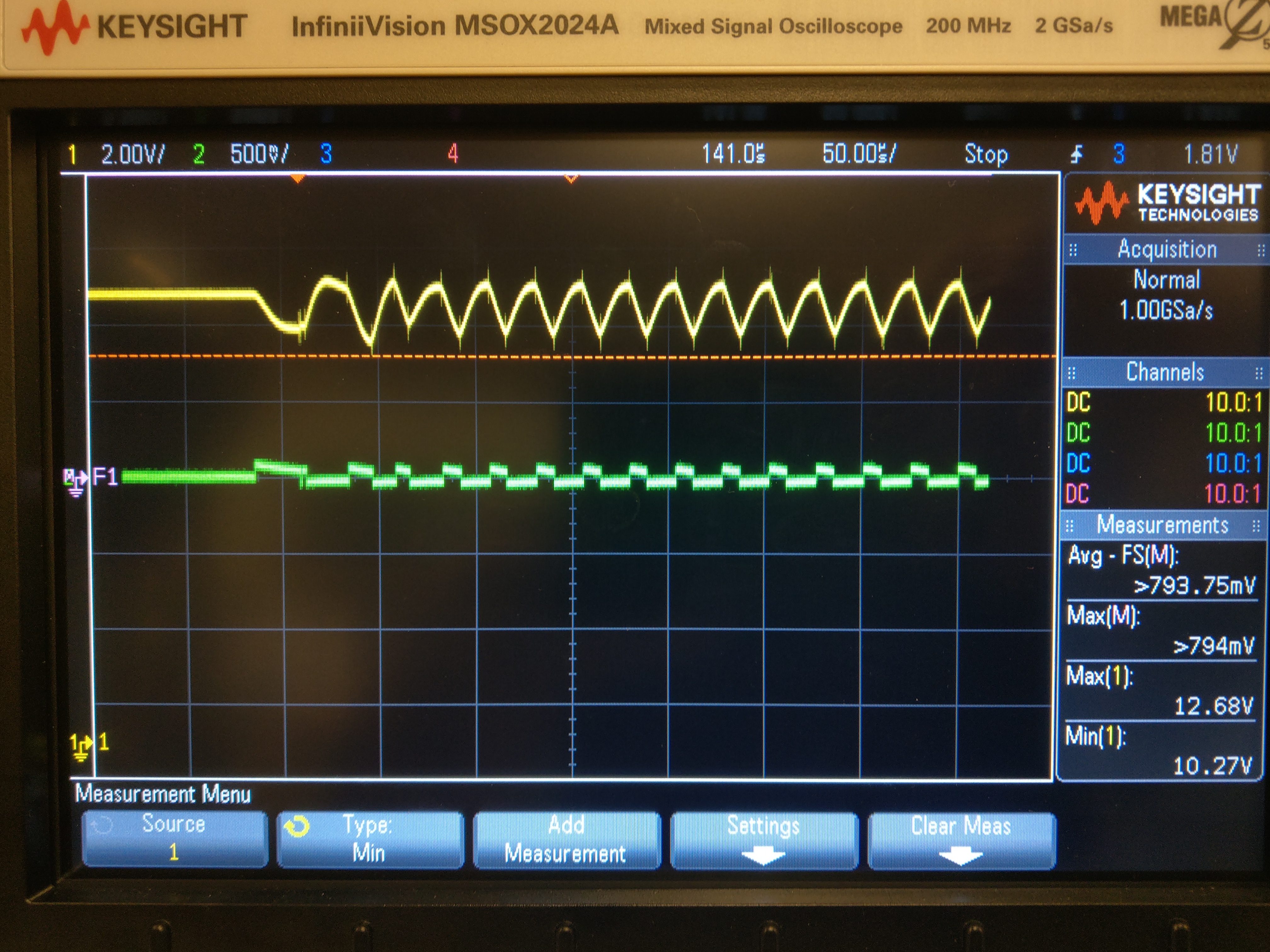
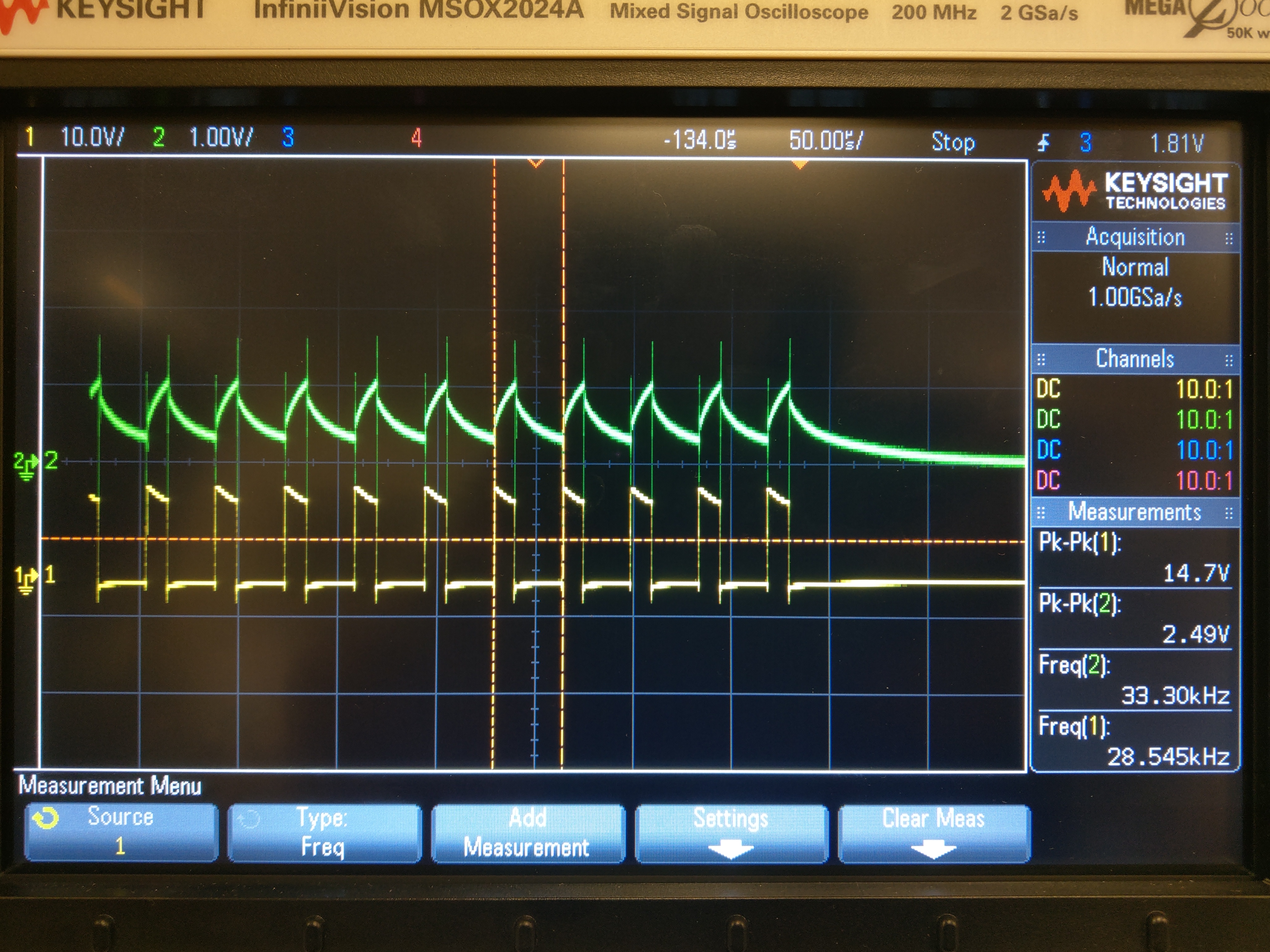
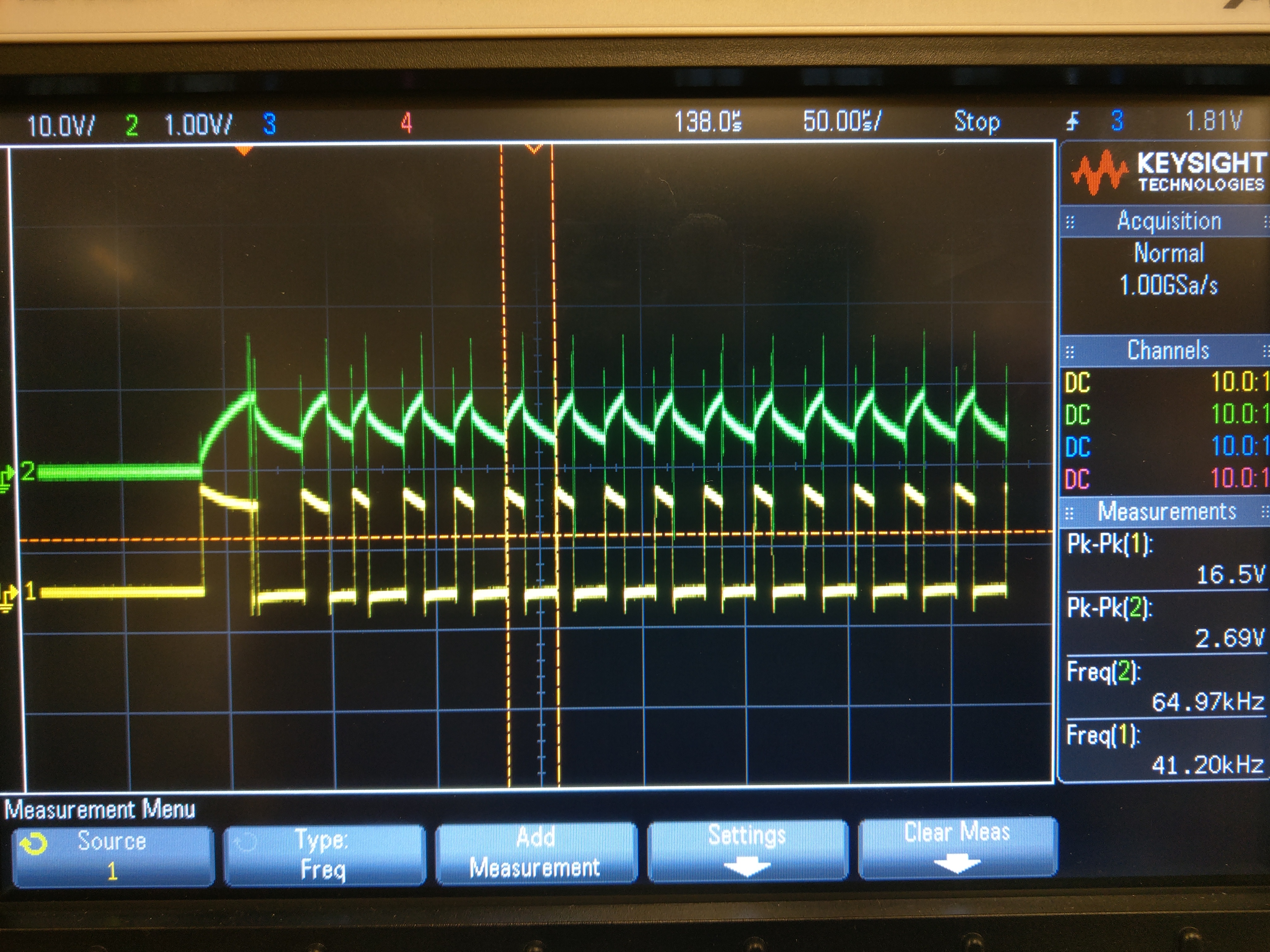
So we are seeing this issue where the motor stalls on higher loads only when 100% duty cycle is used at the input. But it can lift the same weight if a 99% duty cycle is used.

We have seen this issue on multiple of our products, so I don't believe it is a one-time bug.

I can send a schematic privately, but it is very similar to the recommended setup in the datasheet. We have only added an inductor and 2 capacitors on the motor lines to reduce back EMF

Please let me know if you have any ideas of what might fix this,

Thank you, Mike

  • Hello Mike,

    It sounds like for some reason there is a difference in torque between the 99% and 100% test cases. Since torque is a function of motor current, can you take a scope shot using a current probe for each of these cases? I'm hoping you can see some difference that might give a clue to why this happens.

    If you have extra voltage probes, please show the VM, OUT1, and OUT2 voltages. For VM, measure as close to the IC pin as possible.
  • Hey James,

    Thanks for the reply.

    I've attached 2 captures. The yellow and green lines represent the voltages measured on either side of a shunt to the motor.

    The purple line shows the difference between these 2 probes, or effectively, the voltage across the shunt resistor.

    The values can be seen on the right side under "Measurements"

    The value of the shunt resistor is 0.01 ohms.

    This image was captured when stalling the motor at 100% PWM. The shunt resistor shows a voltage of 49mV (50mV for simplicity). This equates to roughly 5 Amps to the motor. (0.05 / 0.01)

    This image was captured when pulling the same weight, but running at 99% PWM. The 120mV equates to about 12 Amps to the motor. (0.12 / 0.01)

  • Here are the captures of the Vmotor supply to the driver IC

    This is stalled:

    This is a successful lift:

  • Here are 2 captures of the OUT1 and OUT2 signals. Green is Out 1, Yellow is Out2 on both captures.

    This is Stalled:

    This is lifting:

  • The current calculations are not accurate I think because of our shunt resistor. But still I believe less current is going to the motor at 100% PWM, as it cannot overcome the stall torque.
  • Also our PWM frequency is 40kHz
  • Hi Mike,

    Thanks for taking the scope shots. I agree with you that the current calculations are likely not accurate. This device cannot handle 12 A, and it may not be able to handle 5 A for extended periods of time. The overcurrent protection on this device would kick in between 3.7 A and 6.4 A.

    Based on the scope shots you shared of OUT1 and OUT2, I think the average current of the 99% case is higher. When you run at 100% duty cycle, you can see the device's fixed off time of 25 us for current regulation. When you run at the 99% duty cycle, your PWM control signal is offset from the DRV8871's current regulation timing. In the 99% case, your off time is less than 25 us. From the scope shots of the OUTx pins, it looks like the PWM pulse off time interrupts the current regulation timing, which gives you a larger average current. The 99% scope shot shows the device switching more frequently than the 100% scope shot.

    I think your motor might have low inductance which is causing you to have large ripples in the current. The large ripple is causing your average torque to be lower. I think the fix would be to find a way to have a lower current ripple or larger average current. Here are some suggestions:

    - Test on a different motor
    - Change supply voltage (my guess is that decreasing it might help)
    - Regulate the current using PWM rather than the integrated current regulation. You will need your current-sense feedback for this.
    - Increase PWM frequency, but still have it set to a high percentage.

    I recommend using a current probe rather than a sense resistor when debugging this torque/current issue. This will give you better insight into exactly what happens with the current.
  • Thanks for the advice. I'll start working through these suggestions and let you know how it goes.

  • Reducing the supply voltage seems to have fixed this issue. Thank you!