This thread has been locked.

If you have a related question, please click the "Ask a related question" button in the top right corner. The newly created question will be automatically linked to this question.

DRV10987: Phase resistance & Phase to Phase Kt settings

Part Number: DRV10987

Hello TI Community,

I have a BLDC motor whose parameters are typically as following :

Phase resistance = 1.44Ohms (tolerances ==> R = Min. 2.59 Ohm / Max. 3.17 Ohm)

Phase to Phase Kt = 39mV/Hz (tolerances ==> Kt = Min 34,8mV/Hz / Max 43.2mV/Hz)

The lookup tables for DRV10987 allow me to set as nearest values for :

Phase resistance = ... / 1.2416 / 1.3968 / 1.552 / 1.7072 / ... (Table 3 page 22 of datasheet)

Phase to Phase Kt = ... / 33.12 / 36.8 / 40.48 / 44.16 / 47.84 / ... (Table 4 page 24 of datasheet)

So is this DRV10987 driver suitable for my motor knowing that I cannot exatly make the looktable settings match perfectly to my motor's parameters ?

Can one give me an percentage of tolerance for those two parameters seen from his knowledges/experimentations in BLDC motor driving ?

I have several pieces of the same blower and I face stall effects while using the same driver with the same settings and I have to adjust each time the driver for a precise blower.

Best Regards,

Marc

  • Errata : Phase resistance = 1.44Ohms (tolerances ==> R = Min. 1.295 Ohm / Max.1.585 Ohm) [divide values by two]
  • -Is the "phase resistance" measurement phase to phase or phase to Center Tap? The resistance entered into driver is phase to Center tap.
    -From my experience, that kt range shouldnt be an issue, but im not sure about the resistance range. Can you tell me what exact fault triggers? I would also recommend trying to double the pwm output which should give better control of the motor.
  • Hi Sammesh,

    this is phase to phase measurement and then I divide the value obtained with the multimeter by two and I enter the result into the driver, no problem to understand for me.

    Please find attached the evolution of current on Phase V when starting the motor with the config as set from §4.2 to §6.1 of the TI tuning guide (working with DRV10987EVM)

    I guess that kt = 40,48 and kt=44,16 are the best suitable values for my motor, what do you think by viewing the screenshots (power set to 300 in a range from 0 to 511) ?

  • Hey Marco,

    1) I dont understand what the scope captures are showing so please help me in understanding them. You say they show current on phase V when starting the motor, but the scope captures show Ch1 as voltages.

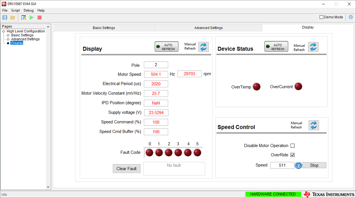
    2) If you want to find an appropriate Kt, use one in the middle of the range of kt's of the motor. So I would use 40.48 mV/Hz. To verify how accurate it is, go to the display tab of the gui and see how well the measured "Motor Velocity Constant" matches the entered kt when running the motor.

    3) If you tell me what fault is triggering, I can help you more.

    Sincerely,
    Sanmesh U.
  • Hello Sammesh,

    1) I use an AC current transducer to catch the evolution of the current, the AT 5 B10 (see attached datasheet)

    2) I enter 40,48 into the driver and obtain following values for different commands :

    Cde =              -      measured kt =

    100 - 40.8

    200 - 39.4

    300 - 35.3

    400 - 31.2

    500 - 26.1

    511 - 25.7

    3) There is no fault triggered, the aim of my post is to know if the required tolerance of the DRV10987 (because of "huge" jumps" between available values in the lookup tables) will be suitable enough to fine tune my parameters to obtain a standard tuning matching for 10.000 to 40.000 motors a year (whose tolerance for PtoP R and Kt are as mentioned in my first post).

    Best regards

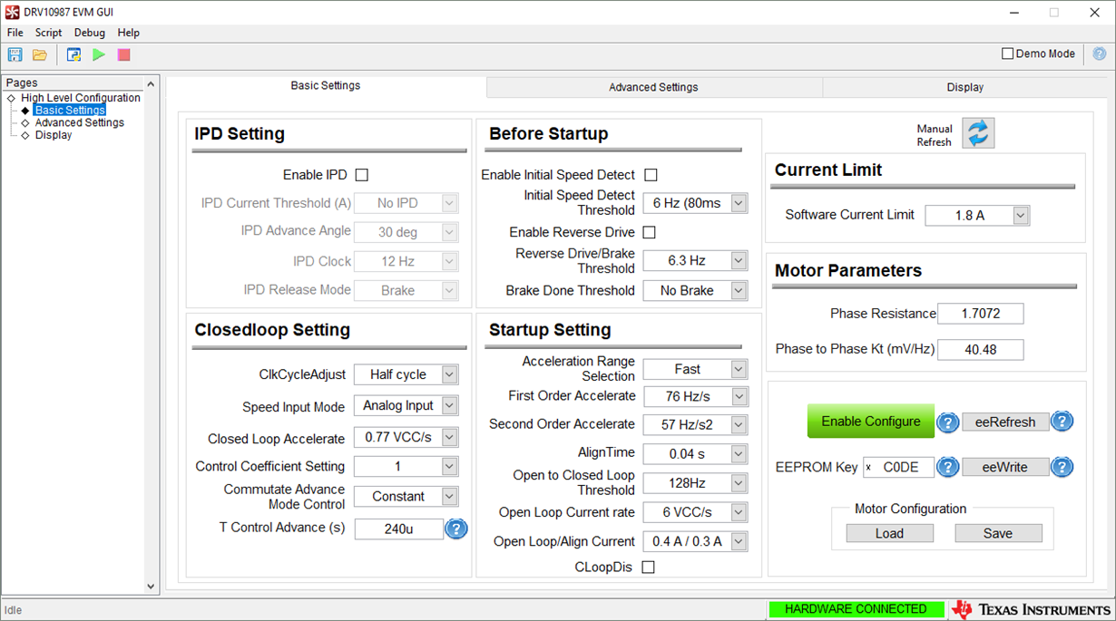
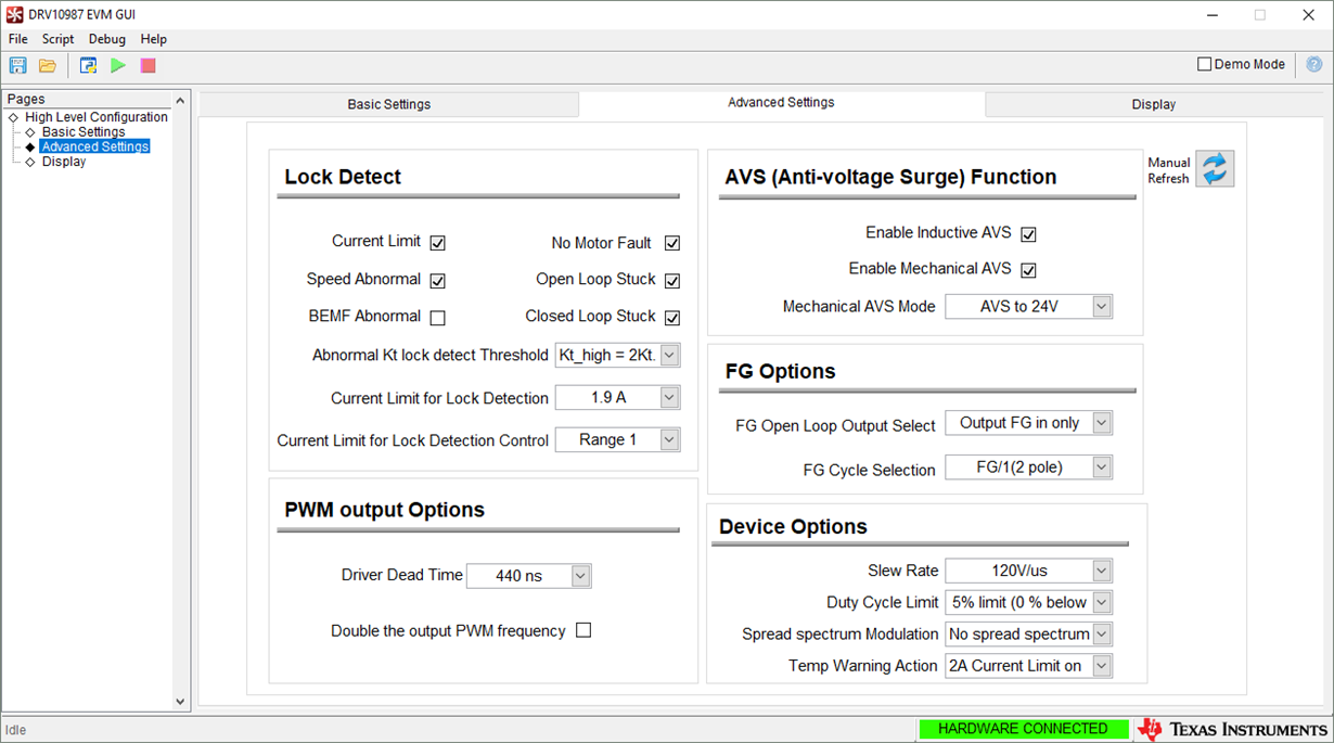
    PS : here my paramaters obtained after a long tuning session where the motor runs good enough seen from my understanding of your tuning guide. The "device options" section is not enough clear to me because of poor explanation content about it in your guide.

    AC current Transducer - 2149965.pdf

  • 1) From my experience, the phase resistance variation of Min. 2.59 Ohm / Max. 3.17 Ohm and the kt variation of Min 34.8mV/Hz / Max 43.2mV/Hz should be tolerable, but if possible, verify it as well. I will also verify with my team.

    2) In your first post, you said "I face stall effects while using the same driver with the same settings". Did you not see locks trigger at these stall points? If you did, what were the locks? If you didnt, this might indicate that the there was a locked rotor condition in the open loop and thus the stall problem has little to do with the kt and R variation. You should adjust open loop instead by making the open loop accelerations slower (right now you set them to maximum) and reducing the open to closed loop threshold.

    3) I would recommend changing the driver dead time to 44ns according to the following table in the DRV10987 tuning guide. I would also recommend lowering the open to closed loop threshold to around 38.4 Hz as this lowers the time in open loop at higher speeds and thus lowers chance of locked rotor condition. I have attached this setting.marcoE2E.csv

  • Hello Sammesh,

    I gracefully thank you for having taken time to answer to my requests concerning the DRV10987 Vs the tolerance ranges for Rpp and Kt.

    It works perfectly for a supply range of 24V to 28V with my motors.

    I see that the DRV10987 is the most powerfull driver in the family (50W) with integrated control logic and FETs, but my application will now require more power i.e. higher maximal rotation speed. Today at 28V I am at about 31krpm and I will need 37krpm, so for the same motor, be able to supply it at +35VDC. I obtained that value of +35VDC with an other driver (L6235PD from ST Micro).

    Is it possible to increase the rotation speed of the motor by increasing something else (for example the frequency of driving phases?) than the supply voltage with the DRV10987 or will I have to search for an other driver ? The problem is that in the TI BLDC drivers family, to reach more powerfull applications there dont exists "Ready to use" or "all in one" drivers like the DRV1098X devices.

    Best regards,

    Marco

  • To increase speed rotation:

    1) set the "Software current Limit" to Disable and set the "Current Limit for Lock Detection" to the max of 3.2 A. 

    2) Try doubling the output pwm frequency and see if it increases the speed.

    Let me know if those two things help you reach your target speed.

    3) Vary T control Advance (s) to get more optimal driving and hopefully faster speed.

    To estimate the max speed you can go at a certain Vcc, use the following equation, but switch the places of motor velocity constant and maximum motor speed, so that you are solving for max motor speed.

    Sincerely,

          Sanmesh U.

  • Hello Sammesh,

    I quote your questions below and give answers in blue :

    ""

    To increase speed rotation:

    1) set the "Software current Limit" to Disable and set the "Current Limit for Lock Detection" to the max of 3.2 A. 

    I worked around this parameter this week before your last post and I know that it is impacting the matching of "Speed Command" and "Speed Command buffer" as explained in the tuning guide. So, I have performed my entire tuning with "Speed Command" = "Speed Command Buffer" i.e. Current limit = Disable / 3.2A.

    2) Try doubling the output pwm frequency and see if it increases the speed.

    I just performed the try with doubling the output pwm freq. Result = no increase in maximum speed.

    Let me know if those two things help you reach your target speed.

    3) Vary T control Advance (s) to get more optimal driving and hopefully faster speed.

    I worked around this parameter this week before your last post too, and as said in the tuning guide, the aim of "playing" with this parameter is to reach the less current consumption for the same speed while trying to obtain a nice motor driving. Result = I found out the optimal value where the motor does not face "BEMF abnormal" problem and the less current consumption : less than 220µs ==> current increases without speed increase ::: 240 µs ==>is fine ::: greater than 300µs ==> "BEMF abnormal" appears.

    ""

    --------------------------------


    The provider of the motor says his motor has a nominal max speed at 30.000rpm, but it is possible, as explained and experienced this week in my previous post, to "overdrive" the motor by increasing VCC to increase "artificially" max speed. Logical consequence seen in the formula to obtain the Motor Velocity Constant.

    Does Texas Instruments plans to develop a driver like the DRV10987 but enable to be supplied with a voltage higher than +28VDC ?


    Best regards,

    Marco

  • Regarding your question whether "Does Texas Instruments plans to develop a driver like the DRV10987 but enable to be supplied with a voltage higher than +28VDC ?", let me check with my team. Response may be delays because of holidays.
  • The answer to your question is yes. But if you want more details, feel free to connect with me through e2e so I can give details as needed.