This thread has been locked.

If you have a related question, please click the "Ask a related question" button in the top right corner. The newly created question will be automatically linked to this question.

DRV8711: Direct PWM. Hi-Z state on both xOUT1 and xOUT2 at the beginning of each period PWM input signal.

Part Number: DRV8711
Other Parts Discussed in Thread: , DRV8704

Hello!

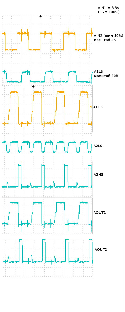
I am using DRV8711 in direct PWM mode. I input signals in accordance with "Table 2. Direct PWM Input Mode Logic" page 12 Datasheet. As you can see on the diagram, the AIN1 signal is constantly kept at a high level, and the AIN2 signal is at 50% PWM. According to the table number 2 datasheet I expect to see on channel A1HS - 50% of PWM 0 - 34 volts, and on channel A1LS a constant voltage of 10 volts supporting the low side is constantly open. But in fact I see that high and low sides are completely closed at the beginning of each period of PWM. You can see it on the diagram. Explain what could be the reason, please.

  • Hi Sergey,

    What is the PWM frequency?
    What are the register settings?
    Are the images vertically aligned?
    Are you using the DRV8711EVM?
  • 180 kHz

    REGISTER = bit11 .. bit0
    CTRL = 1100 1000 0001
    TORQUE = 0001 1000 1000
    OFF = 0001 0000 0000
    BLANK = 0000 0000 0000
    DECAY = 0000 0000 0000
    STALL = 0000 0100 0000
    DRIVE = 1111 1111 1011

    Yes, vertically aligned

    No, it's completly my design
  • Hi Sergey,

    The DRV8711 was intended to drive a stepper motor originally and the PWM feature was added later.
    It was found that when switching from FORWARD/REVERSE to slow decay or slow decay to FORWARD/REVERSE, both outputs were disabled for a short period of time. This appears to be what you have observed.

    The DRV8704 was released to correct this, and it is pin to pin compatible. Please consider using the DRV8704.