This thread has been locked.

If you have a related question, please click the "Ask a related question" button in the top right corner. The newly created question will be automatically linked to this question.

DRV8323: Current sensing problem

Part Number: DRV8323

Hi,

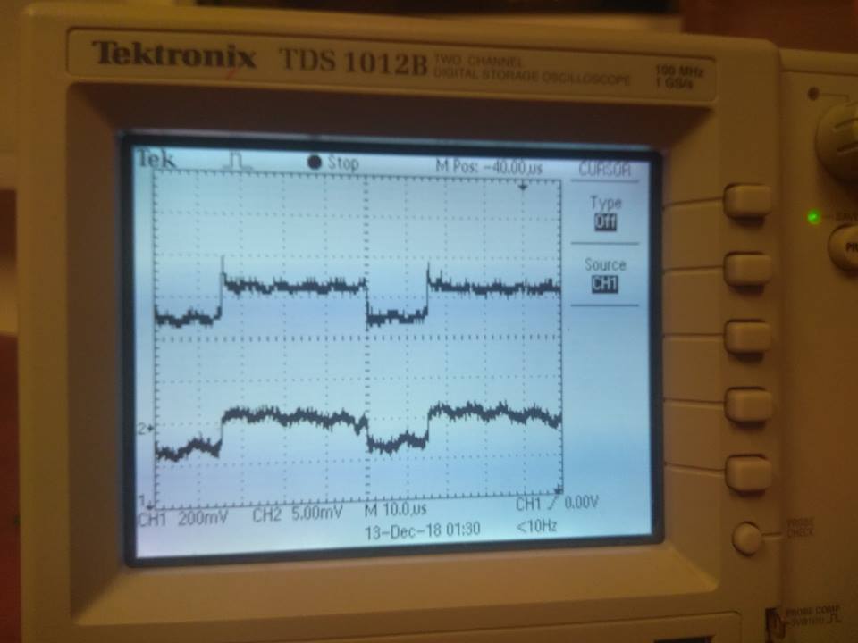
I try to measure motor phase currents. I'm using DRV8323R, and I choose gain 20 by resistor 1M connected between GAIN pin and ground, like it's descripted in datasheet. Shape of the signal is pretty good, but there is something wrong with signal values. I connected my driver to 12V with 1A current limit. Signal value, like on the photo is 1,3V-so the difference between signal and refence level is 350mV-with gain 20 voltage on the current sense resistor should be 17,5mV. I use 1mohm resistor, so that value means 17,5A-impossible with 1A current limit. What can be reason of that issue? I attach signal from SOB pin from the oscilloscope, and screens from board layout-gain resistor connection and and current sense resistor connection. It seems like opamps gains are other than in the datasheet. I check it on 2 identical boards, and there is the same signal level, so it must be connected with gain resistor value, but I have no idea how. Maybe I badly interpreted datasheet? Gain 20 in DRV8323 can be chosen by Hi-Z from pin to ground, like I have marked on the screen?

Gain resistor

Phase current

  • Lukasz,

    You shouldn't need a resistor at all on the gain selection pin. The datasheet should be indicating that the internal resistance to AGND when the pin is HIZ (floating) is >500k ohm. I don't know what the IC does when the pin isn't floated or pulled up/down hard. I will inquire on that.

    2 questions:
    - Have you verified that the resistance between the 2 sense pins is only 1 ohm (no stray resistance)?
    - Have you measured the current directly?

    Thanks,
    Brian
  • Thanks for the answer. Tomorrow I will try without Gain resistor.

    I didn't verified this resistance. I measured on running motor with current control realized by inverter with mcu. So the rms current was less than 1A. Motor phase resistance is 186mohm, inductance 50mH. I didn't make static test with fixed known resistance-I'll do it tomorrow- I didn't have proper resistor for that power.

    I measured current directly with oscilloscope, but without current probe(i measured voltage directly on current sense resistor)-I attach photo. Signals on current sense resistor and output signal from DRV looks good, but the gain is too big. On that photo test conditions was different than above-other current value.

  • I considered traces lengths, it can be reason. I didn't calculated stray resistances before. I'll check it tomorrow
  • Lukasz,

    Any update?

    Did floating the pin make a difference on the gain?

    Thanks,
    Brian
  • Yes, without resistor gain is 20, but measure performance is lower. Now signal has good voltage values, but response time is much longer. I mean that with gain resistor 1M changes on signal measured directly on the shunt resistor appeared faster and shapes of signals were more similiar. But I think that it's good enough and the reason of that difference can be 1000p capacitors in parallel with shunt resistors.