This thread has been locked.

If you have a related question, please click the "Ask a related question" button in the top right corner. The newly created question will be automatically linked to this question.

DRV8305-Q1: Reverse Supply Protection

Part Number: DRV8305-Q1
Other Parts Discussed in Thread: DRV8305

Dear, Sir.

I would like to make sure the Reverse Supply Protection function because I can't

understand well reading the datasheet.

1. I think ;

   Under normal operation, the current sink on VDRAIN will make a triggger to start

   VCPH current source for the external FET gate.

   Under reverse supply condition, the current souce for external will make a trigger

   to stop or start VCPH current sink from the external FET gate.

   I wonder my understanding is correct?

2. I wonder avobe VCPH current sink & source will be syncronous with GHx current

   sink & source?

Best Regards,

H. Sakai

  • Hi Saikai-san,

    VDRAIN does not impact the reverse protection circuit.

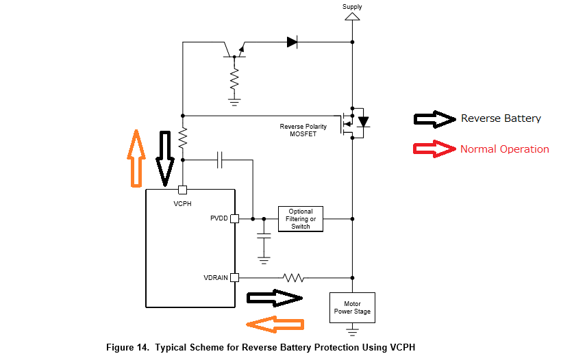
    Under normal supply condition, when EN_GATE goes High, VCPH (supplied from PVDD) will generate the overdrive voltage to turn on the reverse polarity MOSFET.

    Under reverse supply condition, the BJT pulls current out of the gate of the reverse polarity MOSFET to ensure that it stays firmly off.

    Thanks,

    Garrett

  • Dear, Garrett-san.

    Thank you so much for your teaching about the relation of VDRAIN and behavior of circuit.

    I understood, Thank a lot.

    At last, I would like to make sure about VDRAIN function because no detail explanation on DS.

    I am guesiing ;

    When GHx voltage must be discharged to be OFF the external FET due to any kind of fault such

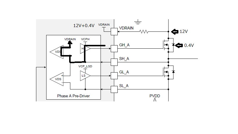
    as VDS_OCP, the curremt sink toword SHx volatge level. The amplifiier is located on SHx & VDRAIN

    with vertual short together, so 12V + 0.4V will be appearred on VDRAIN pin.

    I wonder my guess is correct?

    Sorry to ask you about this kind of matter, but hoping to get your advice.

    Best Regards,

    H. Sakai

  • Hi Sakai-san,

    As described in section 7.1 of the datasheet, the VDRAIN pin is used to accurately sense the drain voltage of the high-side MOSFETs. This is used for the VDS sensing by comparing the voltage from VDRAIN to the SHx pin, as shown in your diagram above.

    When the FET is discharged due to INHx going low or a fault condition, GHx and SHx are internally shorted together. The charge in the gate will then discharge through the body diode of the high side FET. VDRAIN is not involved in switching operation, it is only for VDS sensing.

    Thanks,
    Garrett
  • Dear, Garrett-san.

    Thank you so much for all of your teachings.

    My customer have DRV8305-Q1 EVM, so they are checking the behavior with no load(motor).

    That means SOURCE of high-side FET is open. PVDD = 12V.

    They observed ;

    - Once EN_GATE = ON, SOURCE voltage of high-side FET = 12V(DRAIN voltage) + 0.4V

      without INHx=ON or OFF. Also 12V + 0.4V is observed on VDRAIN pin.

    I would like to get your advice on followings;

    1. EN_GATE.

    a) Will the internal VDS amp be activated by EN_GATE=ON?

    b) What is the supply source for VDS amp? VCPH?

    c) Will the gate pull-down transistor be ON by EN_GATE=ON?

    2. Current Leak from SHx pin.

    a) I think a current leak from SHx pin to body-diode of external FET would be created such

        symptom. How do you think about the souce of the current leak? Discharge current from

        GATE of external FET?  VDS amp input pin? Anything else?

    3. VDRAIN.

    a) 100ohm external resistor is recommended on VDRAIN pin. Is it for the current limit for

        inpu current?

    b) VDARN pin voltage = 12.4V & DRAIN = 12V, so the current will go out from VDRAIN pin.

       What is the purpose of VDRAIN pin & resistor? Current sorce/sink capable?

    Sorry to ask you again & again. Please give your advice one more time.

    Best Regards,

    H. Sakai


  • Hi Sakai-san,

    1. EN_GATE
      1. VDS sensing is only active when INHx/INLx = 1 and when EN_GATE = ON
      2. VDS sensing is supplied from an internal rail
      3. If INHx/INLx is low, then the gate pull-down transistor will turn ON when EN_GATE = ON
    2. SHx Leakage Current
      1. Due to the internal structure of the DRV8305, there is some leakage from VCPH into GHx through the pull-up transistor (even when pull-up transistor is in the OFF state). When INHx is OFF, GHx and SHx are shorted internally through the pull-down transistor, so this leakage current exits the device through SHx. This current then discharges through the body diode of the HS MOSFET, which is why the SHx pin is at VDRAIN + a diode drop.
    3. VDRAIN
      1. This is actually to limit negative voltage on the pin. VDRAIN pin cannot go below -2V, so if VDRAIN voltage goes negative (due to disconnect of VDRAIN from VBAT or similar condition), the resistor will limit the current flow from GND through the ESD diode on VDRAIN to prevent a voltage <-2V
      2. See a.

    Please be advised, I'll be out of office for the next two weeks due to the holidays, so further responses may be delayed.

    Thanks,

    Garrett

  • Dear, Garrett-san.

    I appreciate all of your valuable information # advice.

    I have explained to the customer based on your information. Almost, they have agreed.
    Remaining is just one point;
    You clarified " some leakage from VCPH into GHx through pull-up transistor".
    They measured the voltage ramp-up on the external capacitor, so the current
    level would be mA order not to be uA order.
    Is it possible to roughly clarify the leakage current level?

    It is no problem your reply to be after your holiday.
    I am expecting your understanding & help one more time.

    Best Regards,
    H. Sakai
  • Dear, Garrett-san. 

    Sorry to urge you about this kind of matter, but I am hoping to get your

    support one more time against my remaining question on the previous mail. 

    Best Regards, 

    H. Sakai

  • Hi Sakai-san,

    This leakage will change depending on temperature, and depending on the voltage difference between VCPH and SHx. This isn't a spec item, so there's no characterization measurement or test for this leakage, but based on design expectation, SHx leakage range is around 100-600uA.

    Thanks,
    Garrett