This thread has been locked.

If you have a related question, please click the "Ask a related question" button in the top right corner. The newly created question will be automatically linked to this question.

DRV8301: How to set up F28027F with DRV8301 without external current sensor

Part Number: DRV8301

Hi,

I have successfully replicated  F28027F + DRV8301 design in the custom board. Thank you very much for your forum and support.

In another design, I am trying not to use the external current sensor (due to the space shortage).

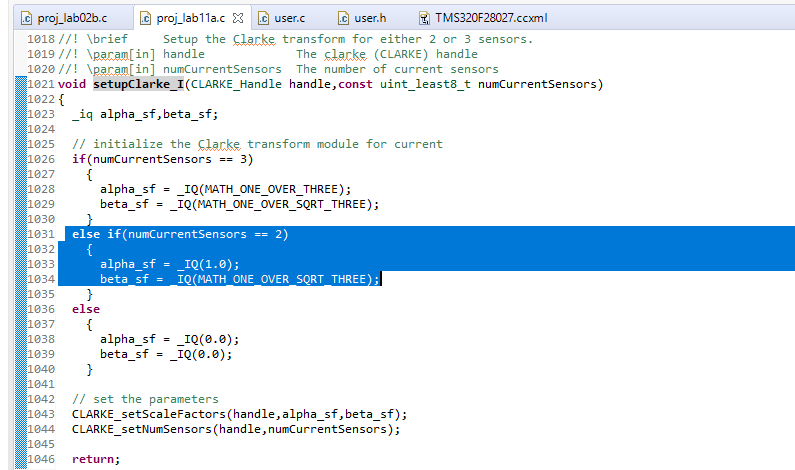
I have changed the number of current sensors from 3 to 2 in user.h file.

Board does not work properly.

Phase C scope (the one without the current sensor) is different (in terms of duty cycle) is different from A and C. 

The motor does not turn.

What other changes need to be done in the program or/and schematics to get it working correctly?

Regards,

Edward.

  • How are you calculating the 3rd phase in software? Have you accounted for this? The estimator is expecting the data for 3 phases, you still have to provide that information

    Sean
  • Hi Sean,

    I was thinking that I am changing the number of current sensors in user.h from 3 to 2, this value goes into the setupClarke_I . After that:

    TI works out coefficients for CLARKE and sets the number of sensors to 2.

    I assumed that by magic TI is calculating the third current from the first two.

    Is not this the case?

    Please hint where to look for the variable responsible for the 3rd phase current.

    Regards,

    Edward.

  • OK, that is correct. You should only need to change current sensors from 3 to 2 in user.h file and recompile. If there is some issue otherwise, I believe there is some other problem. Have you tried diagnosing any issues with your hardware board using labs 1b and 1c?

    Sean
  • Hi Sean,

    Thank you for confirming.

    With labs 1b and 1c, it is a separate issue.

    I don't know why, but I am having problems with them.

    1b turns the motor slowly and overheats mosfets and current sensor resistors (all of them).

    1c simply switches itself off after an attempt to turn.

    2c works fine. now I can identify the motor. Data is almost the same as with 3 current sensors.

    The I offset identified as  -96 (Q24). I set it as 0 in user.h. Is it right? Is it ignored in the code when we have 2 current sensors?

    I will try lab11a and let you know how it goes.

    Is there something specific with lab1b and lab1c for 2 current sensors operation?

    Regards,

    Edward.

  • I have tried lab 11a.
    Now PCB is cool , motor rotates well but heats very quicly without much current drawn from power supply.
    Any suggestions for the quick fix to it, considering mosfet overheating with lab1b?
    Regards,
    Edward.