This thread has been locked.

If you have a related question, please click the "Ask a related question" button in the top right corner. The newly created question will be automatically linked to this question.

DRV10983Q1EVM: Motor not moving

Part Number: DRV10983Q1EVM
Other Parts Discussed in Thread: DRV10983-Q1

Hi there, 

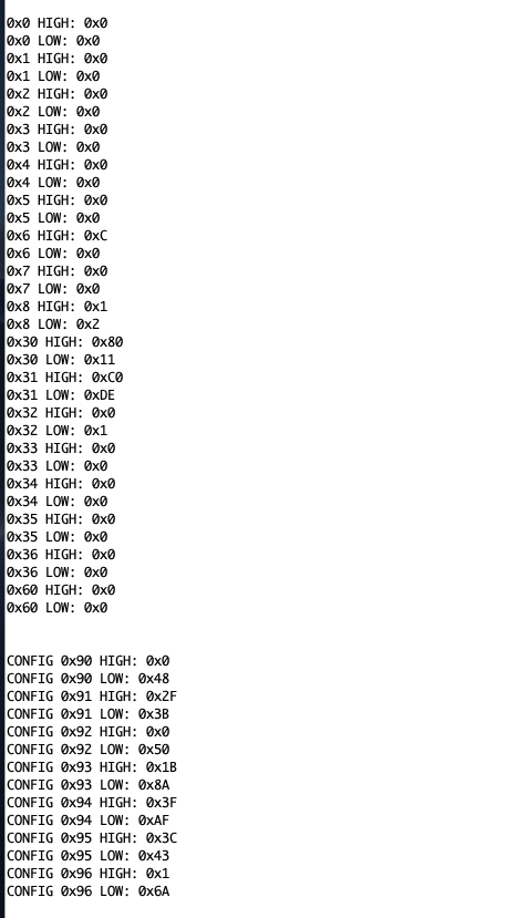
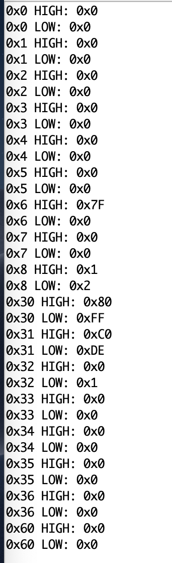
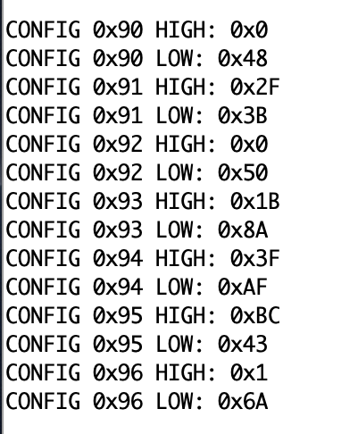
I have been trying to drive a bldc motor with the drv10983Q1 chip for the past couple days with no success. I have been successfully able to communicate with the device over I2C, and I have set the required registers as specified in the datasheet. I set the speed control register but the motor does not move and the MotorSpeed register reads 0x00. Here is a picture of the read register values. I am not sure what I have done wrong. 

I am using 24V supply (which I have measured and is correct) and the current I am drawing is what approximately what is expected according to the datasheet.

Any help would be greatly appreciated :D

  • Hey Isaac,

    1) For easiest evaluation of the device, I would suggest looking at using DRV10983-q1 EVM kit. There is a GUI that makes it easy to tune the device to spin your motor.
    2) In your I2C commands image you gave, can you tell me what the "High" and "Low" means? Also are all those writes? If you answer these questions, then I will be able to read your I2C commands a little better.
    3) "The DRV10983-Q1 device can also command the speed through the I2C serial interface. To enable this feature, the OverRide bit is set to 1." Make sure you do this,
    4) The motor wont spin if it goes into lock. Check if it goes into lock by checking the following CONFIG5 Register (address = 0x94). There is a tuning guide for configuring the device to spin your motor properly so no lock condition occurs (www.ti.com/.../slvuav9.pdf).
    5) Sending a scope capture of one of the phase currents of the motor will help me debug what is going on, if needed.

    Let me know if any of this helps.
  • By high I meant bits 15-8, and low = bits 7-0. The override bit is set to 1 and the motor is not in lock. I cannot send you a picture of the scope output because the chip is not outputting anything from pins U, V, or W (even though the speed is set).

    Do you have any other ideas on what the issue might be, or is there any additional information I can send you to help me with this problem?

    Thanks.

  • Hey Isaac,

    1) Easiest thing to do is when you try to run the motor, please read all of the registers and send them to me, so I can see what potentially is going on.
    2) Right now, the speedctrl is set very low (0x11 or 17/511 = 3% duty cycle). Please try setting the speedctrl to max = 0x81FF or 511.
    3) Sometimes, disabling, then enabling again the Override bit will refresh the device speedctrl.
    4) See whats in the speedcmd and spdcmdBuffer registers.

    Sincerely,
    Sanmesh U.

  • Hi there,

    Here are the register values. I'm setting the speed to 0xFF, but the motor does nothing, the SpeedCmd value is changing, but nothing is being output on any of the phases.

    Config register values

    I am able to successfully read and write eeprom values, the only strange behaviour I have encountered is that the SupplyVoltage register (0x05 LOW) is 0x00 even though the VCC is at 24V. 

  • Is there any sort of sample code that can be used to simply get the motor spinning in the open loop mode?
  • 1) The following behavior is abnormal:

     a) The supply voltage register reads 0x00, even though Vcc is applied.

     b) although the speedctrl is set = 50% (FF) and the speedcmd also shows 50% (7F), the actual speed and motor speed registers indicate zero speed and the speedcmdBuf = 0 as well.

    Can we make sure the device isn't damaged?

    a) Just confirm again what is the Icc or current being drawn by the device?

    b) See what voltages are on Vreg, V3P3, and V1P8. If they are abnormal, it ould indicate circuit damage.

    2) Regarding your question on whether there is any example code to get the motor spinning in open loop, I can confirm that your eeprom write commands you set should get the motor spinning, but you need to set CLoopDis = 1. So the EEPROM Writes to the config registers should be like below:

    GUI.write_register("DRV10983Q1","CONFIG1",0x48)

    GUI.write_register("DRV10983Q1","CONFIG2",0x2F3B)

    GUI.write_register("DRV10983Q1","CONFIG3",0x50)

    GUI.write_register("DRV10983Q1","CONFIG4",0x1B8A)

    GUI.write_register("DRV10983Q1","CONFIG5",0x3FAF)

    GUI.write_register("DRV10983Q1","CONFIG6",0xBCC3)

    GUI.write_register("DRV10983Q1","CONFIG7",0x16A)

    GUI.write_register("DRV10983Q1","SpeedCtrl",0x80FF)

    To visualize your settings, they are below:

  • Thank you for the reply I will try creating something similar to the example code.

    As far as answering your questions, I don't think the chip is damaged as I tried a new chip and had the same issues. The chip is drawing approximately 20mA at 24v, yet the supply voltage register indicates 0x00 so I'm not sure what the issue is there.

  • That Icc of 20mA is greater than the electrical spec max. It may be because of inaccuracies in measuring Icc. but that's just something to keep in mind, I would recommend just checking Vreg, V3P3. and V1P8 as well just to make sure everything is working fine. It could be that the board you are using has some problem, and that is why when you switch in different chips, they all fail. It's just a suggestion.

    Also make sure you are using the typical application schematic below as in the datasheet:

  • Alright I'll check those values. Thanks for all the help and suggestions I appreciate it.
  • alright I got a value of V1P8 = 2.1V, V3P3 = 3.9V, and VREG = 5.7V. Is there something other than the board design that might be causing this to happen?
  • 1) Those voltages are above the maximum values in the electrical spec as shown below.

    This can be because of improper measuring equipment or something wrong in the schematic, maybe particularly the external components related to the Vreg and SW pin.

    As mentioned before, follow the recommended application circuit. Also follow the recommended components table below.

    2) If you are still having trouble with that board, we have reference boards you can build or use as reference. 

    Find "hardware design files" on this page ( http://www.ti.com/tool/DRV10983Q1EVM 

  • Ya, my design is identical to the reference design, so I'm at a loss, but I'll triple check the pcb to see if there's something I missed
  • I have rechecked my pcb and it is not possible that the pcb is causing the issues I am encountering, my design is identical to the reference design, and I have remeasured the values at V3P3, V1P8, and VREG and they are within the maximum allowable values. All register values seem fine, except the supply voltage register is reading zero and I am not getting any output. I am not sure what to do next as I have followed every step of the datasheet and the chip is not working as it should be

  • Ok, let me talk with my team to try to figure this out.
  • This issue has become somewhat of a bottle neck for my team and I, is it possible for you to send us an evaluation board for free or perhaps discounted so we can move the project forward?

  • Hey Isaac,

    Before that, please try the below. I accidentally didnt send this response.

    My best guess:
    1) Please check VCP voltage. It could be that this is damaged and causing the voltage on the motor output stage to be damaged. This is my best guess on what's happening

    Other guesses:
    2) Even if it doesn't look like the DRV10983q1 is trying to spin the motor, it could be that the driver is trying to spin the motor too short of a time before the motor can actually move. Please give scope capture of phase voltages to see if there is any voltage at all.
    3) Make sure that the thermal pad is soldered properly
    4) Maybe the inner adc circuitry is damaged. You can check this by putting the speedcntrl in analog mode and applying a voltage and seeing if it translates to a speed cmd in the registers.

    Let me know if this helps.

    Sincerely,
    Sanmesh U.
  • Nothing is output on the scope, the VCP voltage seems fine, the thermal pad is soldered, and the adc seems to be working fine. I dont want to waste any more time on this issue as I need to move on. I am going to order the evaluation board and a discount would be much appreciated, but if not I understand.

    Thanks for all your help so far, and for the quick and thorough response.

  • Hey Isaac,

    I have asked our marketing department to see if we can give a discount.
    Sorry I couldn't help you figure out the issue. Let me know if you were able to figure it out, as it will help others as well to see how you fixed the issue. I'll mark this resolved for now.

    Sincerely,
    Sanmesh U.
  • Hey Isaac,

    If you haven't already bought an evm, we can provide one for u.

    Sincerely,
    Sanmesh U.