This thread has been locked.

If you have a related question, please click the "Ask a related question" button in the top right corner. The newly created question will be automatically linked to this question.

I found extra diode in servo drives outputs!

Other Parts Discussed in Thread: DESIGNDRIVE

Hi every one 

Good day!

I found extra diodes , Relay and Resistor in servo drives outputs(U,V,W) .please kindly take a look at picture...in pink section.

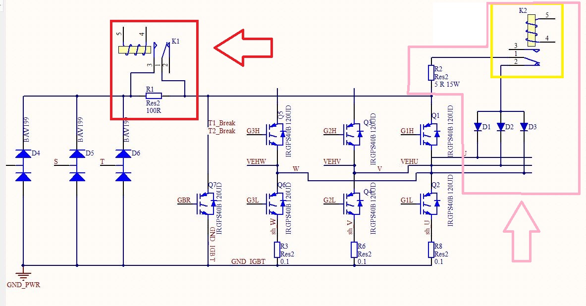
a:why these items should be added ?

b: when K2 should be connected ?when K2 should be disconnected?

c:I think these diodes are controlling DC Bus(in order Not to goes too high) sort of DC break is that right? 

d: why K1 (Soft Start relay) is in Power(+) line while in inverters is in Ground( -) line?

I would be happy if you explain about it .

Regards.

Dave.

  • Hello Dave,
    We need a part number or TI Design number, of whatever you are looking at.
    This will allow proper routing to the team who owns the design.
    Thank you
  • Dear Ed Walker,

    Here is the point I saw this design in most of Servo drives, but in TI design which are TMDXIDDK DesignDRIVE and HVkit do not have this Components (diodes.Relay and Resistor)!!!
    So do we need to add this component if use TI design for our Servo Drive design?
    Or this IGBT power module( PS21765) does not need that?

    Thanks for attention.

    Dave.
  • Thank you Dave,
    This belongs to our C2000 processor team and has been assigned.
    Since it is Sunday you may not receive a reply until Monday.
  • It's not for DC/AC output, just for the AC/DC rectification input using a relay and resistor to suppress surge to the filter capacitor. The resistor will be shorted by turning on the relay if the filter capacitor has been charged.

    Often, it is called inrush delay circuit also, the surge of current that charges the smoothing (filter) capacitors can damage the rectifier diodes when the power supply is first turned on. To limit the surge, a limiting resistor is used to limit the maximum inrush current. After a short delay time, the limiting resistor is bypassed by the relay.

    You might have a look at below link if you have any further questions.

    https://e2e.ti.com/blogs_/b/powerhouse/archive/2015/03/31/powertips-how-to-limit-inrush-current-in-an-ac-dc-power-supply

  • Dear Lu
    I know about that .
    My question is why in servo drive is in DC+,but in inverters is in DC-(Power GND)

    Please answer this question:
    most of servo drives has pink section(D1,D2,D3 and R2)why? would would you please explain about it ?

    regards
    Dave.

  • As you mentioned, there is no such circuit on TI EVM kits, that should depend on a customized requirement. Sorry, we didn't have any idea about this.
  • It's been a week since we heard from you, so I am assuming you no longer need clarification for your question that will be marking this thread as closed. You can reply with a post or create a new thread if you have any further question on this topic. Thanks.