This thread has been locked.

If you have a related question, please click the "Ask a related question" button in the top right corner. The newly created question will be automatically linked to this question.

DRV2605L: Testing Circuit on PCB by driving ERM motor

Part Number: DRV2605L
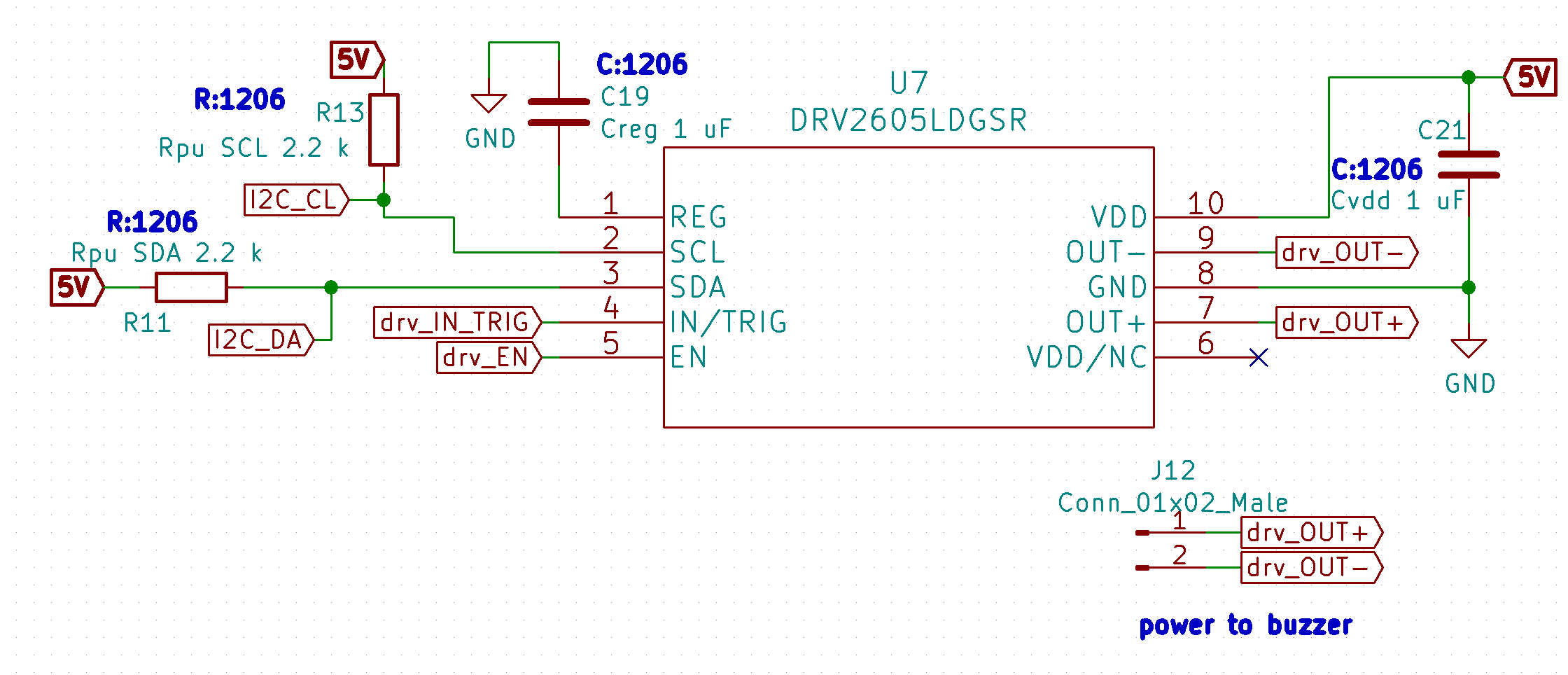
Other Parts Discussed in Thread: DRV2605

Hello! I am using the DRV2605L haptics driver on a PCB to drive an Adafruit vibrating mini motor disc (https://www.adafruit.com/product/1201not specify). The driver is controlled by inputs from an MSP430 microcontroller. I would like to test the functionality of the haptics driver by hooking it up to the ERM and running the simplest possible code on the MSP430 to just turn the motor on. However, I am finding the operational modes (open-loop, closed-loop unidirectional and bidirectional) and the initilization procedure described in the datasheet to be quite confusing.

I was thinking of using open-loop mode for ERM but from what I understand this will not allow me to take advantage of the waveform libraries. To test the functionality of the circuit, this would be OK, although I might want to use waveforms later. The datasheet is a bit hard to follow on how to initialize the DRV2605 driver and use it to turn on an ERM motor, and so my question is if there is a quick start guide form this particular application or a simple program that I could run to make sure that the driver can communicate with the microcontroller and ERM successfully.

Also, am I correct in assuming that all documentation for the DRV2605 is also valid for the DRV2605L with only a few differences such as the lower input voltage range for the DRV2605L? 


  • Hi, Alex,

    Welcome to E2E and thank you for your interest in our products!

    Usually, all the documentation of our devices is located in the technical documents section of our product folders:

    http://www.ti.com/product/DRV2605/technicaldocuments

    http://www.ti.com/product/DRV2605L/technicaldocuments

    I would suggest to start with the document below. This is a setup guide that could be useful for your case.

    http://www.ti.com/lit/an/sloa189/sloa189.pdf

    I hope this helps you. Please let me know if you have additional questions or comments.

    Best regards,
    Luis Fernando Rodríguez S.

  • Thanks for the quick reply, Luis.

    I looked through the documentation prior to posting here and will continue to reference it, however at time the documents can be a bit unclear. For my application, I am using the haptics drive to buzz the ERM whenever the microcontroller picks up a signal from a sensor. I would like to trigger a waveform by having the microcontroller assert the GO bit when it sees the signal from the sensor.

    In order to use the waveform libraries, I would need to use closed-loop mode, correct?

    The ERM auto-calibration example in section 2.2.1 of the set-up guide is only for closed-loop mode, correct?

    Only closed-loop mode can use these features because open-loop mode is not compatible with the waveform libraries and the auto-calibration features (is this feature the same as auto-level?)
  • Hi, Alex,

    Regarding your question about the waveform libraries, the DRV2605L has seven internal-ROM libraries. Six of them are designed to operate in open-loop mode and the remaining in closed-loop for LRA (more details in 8.3.5.2 Internal Memory Interface section: www.ti.com/.../drv2605l.pdf ).

    The example in section 2.2.1 of the set-up guide is configured for open-loop. In the Register Control 3, the bit 5 is configured to use the open-loop. However, we suggest to use closed-loop mode instead of open-loop since the EMF parameter is determined by the closed-loop algorithm in a better way.

    Best regards,
    Luis Fernando Rodríguez S.