This thread has been locked.

If you have a related question, please click the "Ask a related question" button in the top right corner. The newly created question will be automatically linked to this question.

DRV2605L: Driving an LRA using analog input

Part Number: DRV2605L
Other Parts Discussed in Thread: DRV2605

Hi,

Is it possible to input a sine wave (1.8V peak-peak) and see the same sine wave output from the DRV2605L? Is there a way to define the maximum amplitude of the output? e.g. 1.8V input => 3V output.

I have a sine wave as input to the IN/TRIG pin (1.8V peak to peak at 250Hz)

I have the DRV2605L set up to drive LRAs (0x1A register, N_ERM_LRA = 1)

I am in PWM/ANALOG Mode (0x01 register = 0x03)

I have selected analog input (0x1D register = 0xA3)

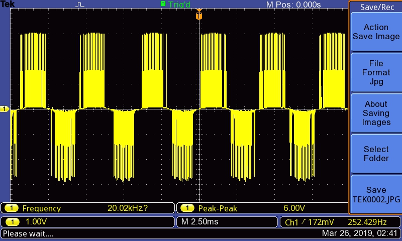
I get the following output:

  • Hi, Stephen,

    Welcome to E2E and thank you for your interest in our products!

    It is possible to get the same waveform from the differential output (OUT+   minus   OUT -). However, you would require to configure the device to drive the LRA load in open-loop mode. In addition, you would need to reduce the overdrive voltage (around 1Vdc) since the output voltage may result in a high voltage.

    Please take a look at the attached script, it is an example of a configuration that uses a sine waveform at the IN/TRIG input.

    Exported at :3/22/2019 5:01:19 PM
    	========Register Dump Start========
    		Reg:[0x0]	=	0xe0		Status
    		Reg:[0x1]	=	0x3		Mode
    		Reg:[0x2]	=	0x0		Real-Time Playback Input
    		Reg:[0x3]	=	0x1		Library Selection
    		Reg:[0x4]	=	0x2f		Waveform Sequencer 1
    		Reg:[0x5]	=	0x0		Waveform Sequencer 2
    		Reg:[0x6]	=	0x0		Waveform Sequencer 3
    		Reg:[0x7]	=	0x0		Waveform Sequencer 4
    		Reg:[0x8]	=	0x0		Waveform Sequencer 5
    		Reg:[0x9]	=	0x0		Waveform Sequencer 6
    		Reg:[0xa]	=	0x0		Waveform Sequencer 7
    		Reg:[0xb]	=	0x0		Waveform Sequencer 8
    		Reg:[0xc]	=	0x0		GO
    		Reg:[0xd]	=	0x0		OverDrive Time Offset
    		Reg:[0xe]	=	0x0		Sustain Time Offset, Positive
    		Reg:[0xf]	=	0x0		Sustain Time Offset, Negative
    		Reg:[0x10]	=	0x0		Break Time Offset
    		Reg:[0x11]	=	0x8		Audio-to-Vibe Control
    		Reg:[0x12]	=	0x19		Audio-to-Vibe Minimum Input Level
    		Reg:[0x13]	=	0x64		Audio-to-Vibe Maximum Input Level
    		Reg:[0x14]	=	0x19		Audio-to-Vibe Minimum Output Drive
    		Reg:[0x15]	=	0xff		Audio-to-Vibe Maximum Output Drive
    		Reg:[0x16]	=	0x3d		Rated Voltage
    		Reg:[0x17]	=	0x2e		Overdrive Clamp Voltage
    		Reg:[0x18]	=	0xd		Auto Calibration Compensation Result
    		Reg:[0x19]	=	0x6e		Auto Calibration Back-EMF Result
    		Reg:[0x1a]	=	0x36		Feedback Control
    		Reg:[0x1b]	=	0x93		Control1
    		Reg:[0x1c]	=	0xf5		Control2
    		Reg:[0x1d]	=	0xa3		Control3
    		Reg:[0x1e]	=	0x20		Control4
    		Reg:[0x1f]	=	0x40		Control5
    		Reg:[0x20]	=	0x30		LRA Open Loop Period
    		Reg:[0x21]	=	0xe7		VBAT Voltage Monitor
    		Reg:[0x22]	=	0x3c		LRA Resonance Period
    	========Register Dump End========
    

    Best regards,
    Luis Fernando Rodríguez S.

  • HI, 

    I tried setting all the registers as per your reply, but the output from the DRV2605 is as shown below. Any suggestions for what I should try next?

    Cheers

    Stephen

  • Hi, Stephen,

    I made more testing on our evaluation modules and it seems that the output signal won't be exactly the same waveform than the input signal. You may get an approached signal with the help of a Class-D filter (RC filter, R = 100ohms, C = 0.047uF suggested). The frequency will be also approached and the voltage must be modified by the DRV2605L registers.

    Best regards,
    Luis Fernando Rodríguez S.
  • Hi, Stephen,

    Could you try with a Class-D filter as I mentioned above? Do you have new observations?

    Best regards,
    Luis Fernando Rodríguez S.