This thread has been locked.

If you have a related question, please click the "Ask a related question" button in the top right corner. The newly created question will be automatically linked to this question.

DRV8838: Current Leakage onto the output

Part Number: DRV8838
Other Parts Discussed in Thread: XTR111

Hi there everyone,

I am driving a tiny coil with a constant current source. In order to be able to reverse the current flow direction at the coil, I've connected the coil to a DRV8838 H-Bridge, which in turn is driven by that constant current source. The issue that I am having is that the measured current at the coil does not match that of the DRV8838 input.

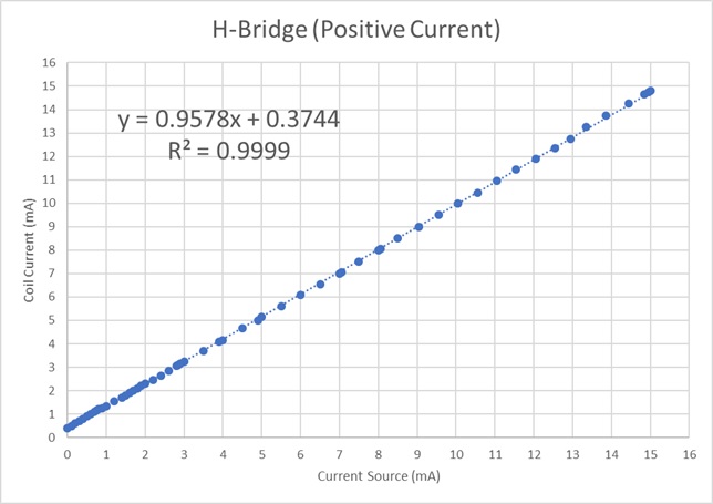
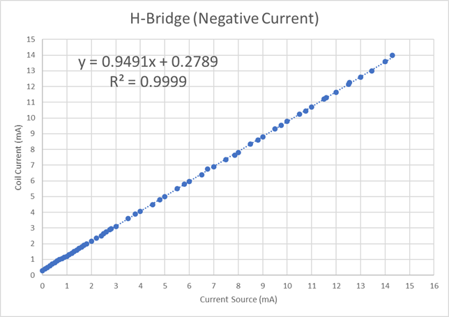
I have taken samples of both parameters in the range of operation that I am running the device at, in both reverse and forward, and the results both show the same trend:

  • Both graphs show an initial current of 0.27 - 0.37 mA, suggesting that there is leak from somewhere else, since the current source is sourcing 0 mA.
  • The slope of both graphs is less than 1, so they both eventually reach a point where I_coil = I_source, this roughly happens at around 6.5 - 7 mA in both cases.
  • Past the 6.5 - 7 mA point, the current measured at the coil starts to be lower than that supplied by the current source. Suggesting that now the current from the current source appears to be sinking somewhere else other than on the coil.

I would really appreciate any insight into why this is happening. At first I suspected it might have something to do with the H-bridge gates leaking current onto the coil circuit, but the situation reversal after 7 mA has got me thinking it might be something else.

Thanks in advance,

Dani

  • Hi Dani,

    Can you provide a schematic of your connections to the DRV8838?
    Are the VCC and VM connected together? If not, what is the VCC voltage?
    Also, do you the voltage at each of the points in your plot?
  • Hi Dani,

    We have not heard from you in some time, and are assuming you have resolved your issue.

    If you have not, please reply to the thread or if the thread is locked select "Ask a related question".
  • Hi Rick,

    This is the circuit diagram:

    Out 1 and Out 2 are connected to a 160 ohm resistor, nSleep, in 1 and in 2 to Arduino PWM outputs, while Vm is supplied by a XTR111 constant current supply (0-2.5V and 0-15mA), Gnd is connected to a common ground rail elsewhere in the circuit.

    Vcc is supplied by the Arduino 5V rail.

    The data shown on the graphs on my first post refer to the current flowing through in 1 and in 2 and the same in reverse.

    Regards,

    Dani

  • Hi Dani,

    Thanks for the information. Can you confirm VM and VCC on the DRV8838 are not connected together? I see the net name on pins 1 and 8 listed as "S$587".
  • Hi Rick,

    They are not connected together. I don't really know why EDA employed the same net name, but the PCB that was physically printed had no connection between them.

    Also, I revised the soldered connections and they seem to be okay. I am not sure about the thermal plate, maybe some excess solder is slightly bridging Vm with the plate and the plate with Vcc? I think that if that were the reason, the device wouldn't function at all, but I can't think of anything else.

    Regards,

    Dani

  • Hi Dani,

    I attempted to duplicate your experiment but was not successful. I only saw a few microamps when the current source was at 0mA.

    I suspect there may be a difference in the setup or perhaps some type of calibration problem.

    Can you provide more details on how you made the measurements. A schematic with the equipment connection would be appreciated.

    Also, it would help to know what equipment was used. What was the model of the current source and other measuring equipment?