This thread has been locked.

If you have a related question, please click the "Ask a related question" button in the top right corner. The newly created question will be automatically linked to this question.

DRV8816: Driver output not being pulled low

Part Number: DRV8816
Other Parts Discussed in Thread: , DRV8872

Hello, 

I am using the DRV8816 Motor Driver to control a 24V Brushed DC Motor (inside of a linear actuator). I am noticing issues with low side not being pulled low all the time.

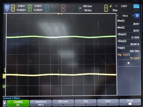
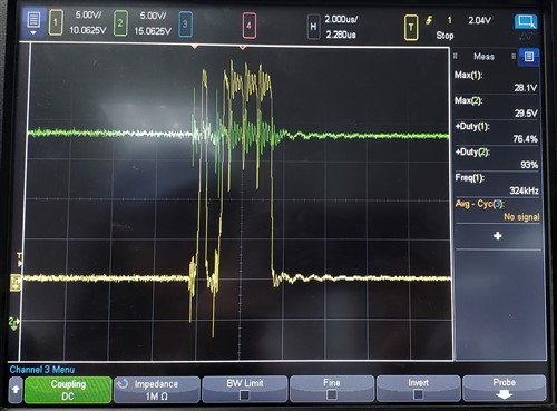
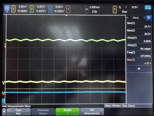
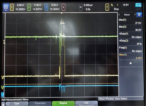
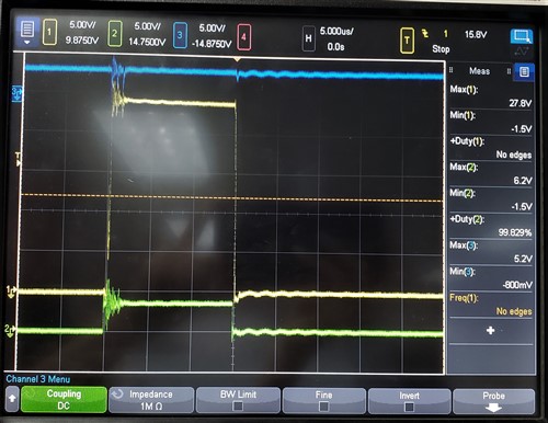
In the first case, I have both EN lines pulled HIGH (3.3V). I have IN1 LOW (GND) and IN2 HIGH (3.3V), so I expect OUT1 to be LOW (0V) and OUT2 to be HIGH (24V). However, I notice that OUT1 will pulse HIGH at times. See first picture and second picture for a zoomed in view of the pulse. OUT1 is yellow and OUT2 is green. The motor will still drive, but I am wondering why is this happening? And is there anything I can do to get rid of this effect?  


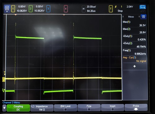
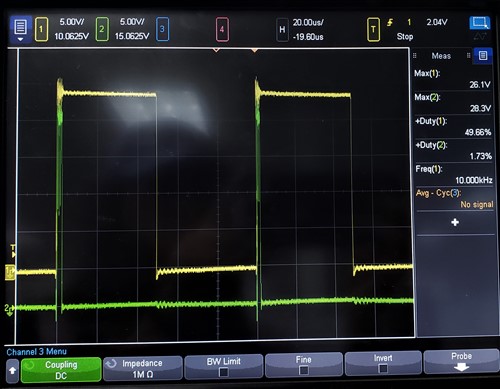
As a followup, I also tried to PWM the inputs and the behavior is even more noticeable. Again I have both EN lines pulled HIGH (3.3V). In the first picture, I have IN1 LOW (GND) and IN2 being PWM (0V to 3.3V) at a 50% duty cycle and 10kHz frequency. You can see OUT2 is being PWMed as expected, but OUT1 is pulsing HIGH at the same time OUT2 goes HIGH. In the second picture, I have IN1 being PWM (0V to 3.3V) at a 50% duty cycle and 10kHz frequency and OUT2 LOW (GND). Again, OUT1 is being PWMed as expected, but OUT2 is pulsing HIGH. Additionally, if I increase the frequency of the PWM signal that seems to increase the period the time the outputs pulse high for. 


Can anyone explain to me what is happening and how to solve this issues? 

  • Hi Grace,

    Our experts will look further into this point and get back to you.
  • Hi Grace,

    The first image shows what appears to be an overcurrent event. Please check the nFAULT signal. With a pullup resistor on nFAULT, the nFAULT is probably going low for ~1.6ms (tocp).

    If this is occurring, please look for a capacitor on the motor leads or inside the motor. The capacitor is usually the cause of this overcurrent event.
    It can also be the inductance of the motor is very low allowing the current to rise very quickly when stalled.

    There are a few options available to correct this depending on the cause (capacitance or inductance):
    1) If the capacitor is the issue, lower the voltage to decrease the inrush current of the capacitor
    2) Add some inductance inline with the motor
    3) If the motor is the issue, change to a different driver that can handle higher stall current
    4) Change the motor
  • Hi Rick,

    I am fairly confident it is not an overcurrent event. I have the entire system hooked up to a power supply with the current limit set to 1A which is far lower than the 3A Iocp (I do not have a SENSE resistor so default overcurrent limit should be 3A). The maximum current draw I observe as well on the power supply is approximately 0.6A when the motor is moving in either direction. I have also checked the nFAULT signal which I have pulled up to 3.3V with a 1.8k resistor. It is always a constant 1.2V (weird that it is not 3.3V, but it definitely is constant).

    Additionally, since the motor is housed within a linear actuator unit, I have no access to the motor itself and cannot change it or check for any capacitor.

    Is it an inherent part of the motor driver that the outputs must default idle HIGH in the brake state?
  • Hi Grace,

    Please provide a scope capture with the nFAULT pin in addition to the behavior in the first image. This will help rule out an overcurrent event. A local bulk capacitor can provide the current during an overcurrent event. The peak current during the overcurrent event can be >3A, but the average current will be much lower.

    "Is it an inherent part of the motor driver that the outputs must default idle HIGH in the brake state?"

    The DRV8816 can set the outputs both high or both low in the brake state. Please refer to Table 3 of the datasheet.
  • Hi Rick, 

    Here is a scope image of the same situation as the first image, and then a zoomed in view with the nFAULT pin in blue. As you can see, this does not appear to be an overcurrent event because the nFAULT pin does not follow normal fault behavior. It's barely even a few microseconds. 


    I ask if the outputs must default idle HIGH because I am following the table in the datasheet and according to the behavior I am observing they don't seem to remain low when inputs are low but always do remain high when inputs are high. 

  • Hi Grace,

    nFAULT is shown as low in all of the images. This is typically an indication either a pullup resistor is not connected.

    Please be sure to connect a pullup resistor to the NFAULT pin. This pullup is needed to determine when a fault occurs.
    Once the fault is detected, the type of fault can sometimes be determined by the timing on the nFAULT pin.

    Would you please confirm there is a pullup resistor on nFAULT, and retake the scope captures at 500us per division. If the fault is an overcurrent, the nFAULT should repeat at a 1.6ms interval.
  • Hi Rick,

    Please look again at the picture. As I stated before, I have the nFAULT signal pulled up to 3.3V with a 1.8k resistor. On the scope I have it set up to 5V/div so that all the signals can fit on one scope and the ground level for the blue signal is indicated on the very left. So nFAULT signal is high and only drops low for a few microseconds. Thus, it is not following the normal fault behavior and is why I am asking this question.
  • Hi Grace,

    Sorry, I mis-read the nFAULT signal. Thank you for pointing this out.

    Let's go back to the beginning.

    Are you using the DRV8816EVM or your own board?
    If your own board, can you provide a schematic of the DRV8816 and the connections?
    Do you see the same response if the device has no load?
    Can you provide a scope capture of IN1, OUT1, and nFAULT zoomed in (5us/division)?
    Both unloaded and loaded.
  • Hi Rick,

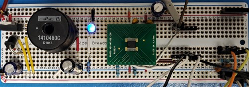
    I am currently using my own board. Right now I am still in the prototyping phase so it's just a protoboard. Below is a picture of what my protoboard setup looks like. On the left is just voltage converter from 24V to 3.3V and the DRV8816 is connected in the middle. 

    Here is a schematic of how I am currently connecting the DRV8816 IC. The input/output ports go to header pins which I then connect to either 3.3V, GND, or the PWM signal (from waveform generator). OUT1 and OUT2 go to the motor.

    No, when the device has no load it operates perfectly fine.

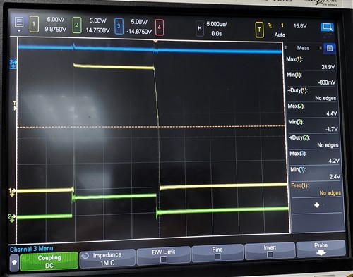
    Here is a scope capture of IN1 (green, PWM at 20kHz, 30% duty cycle), OUT1 (yellow), and nFAULT (blue) with no load. 

    Here is a scope capture of IN1 (green, PWM at 20kHz, 30% duty cycle), OUT1 (yellow), and nFAULT (blue) with motor loaded. 

    My original question has to do with why the output signal that is not being PWMed is not able to be held steady at 0V even when its input is tied to ground. 

  • Hi Grace,

    Thank you for the image. This is very helpful.

    There could be some unexpected noise in this system. Please check the EN1 and the IN1 inputs at the pins of the DRV8816.

    If you see noise on the inputs, please clean up the connections. It is difficult to see the VBB and GND paths in the breadboard.

    Another option available is to use the DRV8816EVM. The EVM can be operated using the onboard mcu or controlled at the testpoints.
  • Hi Grace,

    We have not heard from you in some time, and are assuming your issue has been resolved. If it has not, please reply to this thread or if the thread is locked please select "Ask a related question" at the top right of the screen.
  • Hi Rick, 

    The problem still persists and does not appear to be an issue of noise from grounding. It seems the issue depends on what load is connected. For example I tried connecting an entirely different motor to the same motor driver setup and did not have the same issue. I'm not too sure how different motors load the motor driver differently. 

  • Hi Grace,

    Sorry to hear you are still having problems.

    Motors have different resistance and inductance, and sometimes have capacitors across the windings.
    What are the parameters of the two motors?

    Have you considered ordering the DRV8816EVM for evaluation? The EVM has the ability to be controlled via the on board mcu, or can be controlled via external signals by removing R3 through R6 and connecting to the test points.
  • Hi Rick,

    The initial motor that is causing problems is an internal motor to this linear actuator: https://cdn.shopify.com/s/files/1/0061/7735/7891/files/Medium_Mini_Actuator_PA-09.pdf?12278175527760917360 

    Unfortunately I have asked the company and they can't provide me any specs on the motor itself. 

    The second motor that I used to test that did end up working is this one: https://www.faulhaber.com/fileadmin/Import/Media/EN_1524_SR_DFF.pdf 

    Do you happen to have any intuition about differences between the two motor loads that could cause them to cause the motor driver to behave differently? 

    Since loading seems to be the issue, I didn't think ordering the evaluation board would be helpful/ I have ordered the evaluation board for DRV8872 and hoping that will work instead. 

  • Hi Grace,

    Assuming you have the 24V version of both motors, the motor causing problems can use from 0.5 to 3.5A (No Load current of 0.5A to Full Load Current of 3.5A).

    The second motor has a range of 4mA to 300mA (Nol load current of 4mA and 24V/79.3Ohm = 300mA).

    If you will see as much as 3.5A, please measure the resistance of the first motor (pins 4 to 5). The resistance should be approximately 6.8 Ohms. If much less the current during startup and stall could be higher.
  • Hi Rick,

    I measured the resistance of the first motor and got infinite resistance in one direction and 1.9Mohm in the other direction. This doesn't quite make sense so maybe pins 4 to 5 are not actually directly connected to the motor?

    I measured the resistance of the second motor and got about 70 ohms in both directions.
  • Hi Grace,

    Sorry, there is some confusion on the datasheet.

    There is a two pin connector and a six pin connector. Pins 1 and 2 should be measured on the two pin connector and pins 4 and 5 should be measured on the six pin connector.

    Is it possible you may have read pins 5 to 6? Either way if the current in the motor reaches 3.5A when starting or stalled, the overcurrent protection could activate.

    About 70 Ohms for the second motor could be correct. Usually there is some variation.
  • Hi Rick,
    Yes I was measuring pins 4 and 5 on the six pin connector.
    I just received the evaluation board for DRV8872 and have been testing that today. So far it is working and I'm not seeing the same behavior so I may have to just abandon DRV8816 and go with DRV8872. Thank you for all your help.
  • Hi Grace,

    We are glad to hear the DRV8872 is working for you. The DRV8872 saves a few components since it has a built in charge pump.

    Please let us know if you have further questions.